Description
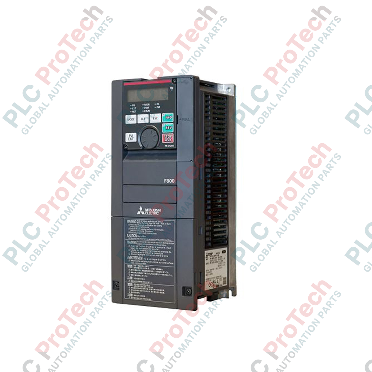
Operating as a high-capacity motor speed controller, the Mitsubishi Electric FR-F840-04320-2-60 is engineered specifically for variable torque load management in demanding industrial processes. This FR-F800 Series Inverter delivers precise control for heavy-duty pumps, fans, and blowers by optimizing electrical energy consumption based on real-time load demand. Engineered with dual-rating structures, the module supports both Super Light Duty (SLD) and Light Duty (LD) configurations to match specific system requirements, ensuring high operational efficiency while protecting mechanical components from start-up stress.
Features
-
Dual Load Ratings: Highly adaptable power stages supporting 432A under Super Light Duty (SLD) and 380A under Light Duty (LD) operations.
-
Advanced Optimum Excitation Control: Continually adjusts the excitation current to its ideal limit, achieving significant energy savings under light load conditions.
-
Integrated PLC Functionality: Supports localized programming and logic control via internal software structures, reducing dependency on external master controllers.
-
Multi-Pump Control: Built-in sequencing algorithms enable direct management of up to four pumps without requiring external option cards.
-
Comprehensive Safety & Security: Built-in STO (Safe Torque Off) safety functions prevent unexpected motor startups during system maintenance.
Applications
- Municipal water treatment plants (aeration blowers, intake pumps, and booster stations).
- Large-scale commercial HVAC installations (cooling towers, chillers, and supply/exhaust fans).
- Industrial clean rooms and manufacturing ventilation networks.
- De-watering operations in mineral extraction and mining sites.
Technical Specifications Table
| Parameter |
Specification Value |
| Manufacturer |
Mitsubishi Electric |
| Model Number |
FR-F840-04320-2-60 |
| Inverter Series |
FR-F800 |
| Input Supply Voltage |
Three-phase 380V to 500V AC (50Hz / 60Hz) |
| Rated Current (SLD) |
432 A |
| Rated Current (LD) |
380 A |
| Applicable Motor Capacity (SLD) |
220 kW |
| Applicable Motor Capacity (LD) |
185 kW |
| Enclosure Rating |
IP00 (Open Type) |
| Cooling System |
Forced Air Cooling |
| Shipping Weight (Calculated) |
120 kg |
| Package Dimensions (Calculated) |
920 mm x 520 mm x 480 mm |
Connections and Interfaces
| Terminal Class |
Terminal Designation |
Functional Assignment |
| Main Power |
R/L1, S/L2, T/L3 |
Three-phase AC power input line connections |
| U, V, W |
Three-phase AC output connections directly to motor stator |
| Control Inputs |
STF / STR |
Forward Start / Reverse Start command terminals |
| RL, RM, RH |
Low, Medium, and High multi-speed selection inputs |
| SD |
Common terminal for digital control inputs (isolated) |
| PC |
24V DC external power supply input/output terminal |
| Analog Output |
AM / CA |
Analog signal outputs for output frequency or current feedback |
Empirical Engineering Insights
Alternative Models & Compatibility
When migrating to the FR-F840-04320-2-60 from legacy platforms like the FR-F740 series, control terminal locations and logic assignments remain highly compatible. However, verify parameter mappings since the FR-F800 series utilizes expanded parameter blocks. Dedicated parameter transfer software (FR Configurator2) must be used to map and scale analog inputs to ensure parity in speed-reference loops.
Application Pitfalls & Engineering Notes
Operating at a continuous output rating of 432A (SLD) produces substantial thermal dissipation. Unrestricted air volume exchange is required in the housing enclosure. Standard panel configurations must allow a minimum clearance of 150 mm above and below the chassis, and the cabinet exhaust rate must prevent the ambient air directly surrounding the heatsink from exceeding 40 degC to avoid automatic thermal current limiting.
Commissioning & Wiring Tips
To protect motor stator windings from reflective voltage wave phenomena, we strongly recommend installing an output dV/dt filter or sinus filter for any motor lead runs exceeding 30 meters. Ensure that the control signal cables use twisted-pair shielded wire and are run in separate conduits isolated from the high-power AC output cables (U, V, W) to mitigate electromagnetic coupling.
Installation Guidelines
CRITICAL WARNING: HIGH VOLTAGE HAZARD
Ensure that the main incoming three-phase AC power lines are fully de-energized and locked out before removing the terminal covers. Allow at least 10 minutes after disconnecting supply power for internal DC link capacitors to fully discharge. Always measure the DC voltage across terminals P/+ and N/- to verify that the charge is below 45V DC before starting internal installation or wiring operations.
1
Mechanical Mount: Mount the unit vertically onto an unpainted, conductive metallic backplate within a secure, dust-free industrial cabinet. Secure all mounting bolts to structural cross-members to support the unit's 120 kg weight.
2
Ground Connection: Ground the inverter chassis directly to the main system PE (Protective Earth) busbar. Ensure the connection path has low resistance and uses a ground wire rated for high fault currents.
3
Power Terminals: Route and crimp appropriate ring terminals onto the input power and motor power lines. Torque all terminal bolts to OEM torque specification to prevent hot spots and resistance losses under load.
4
I/O Commissioning: Connect the control terminal blocks, verifying that the common line (SD) is completely isolated from the PE chassis path to preserve signal integrity and avoid ground loop noise.