Description
Engineered to expand the connectivity of the MELSEC iQ-F controller platform, the Mitsubishi Electric FX5-ENET/IP network module provides dedicated EtherNet/IP and standard Ethernet communication capabilities. Integrating this module into your automation architecture enables the FX5 CPU to act as both an EtherNet/IP scanner (master) and adapter (slave) simultaneously, facilitating seamless data exchange with remote I/O, variable frequency drives, and third-party instruments. Operating on a 24 V DC internal power supply with a low current draw of 110 mA, it delivers high-performance industrial networking without putting unnecessary strain on the system's power budget.
Features
- Dual-role capability functioning as both an EtherNet/IP CIP communication scanner and adapter.
- Supports standard Ethernet communication protocols alongside industrial EtherNet/IP on a single physical link.
- Seamless integration with GX Works3 configuration software for drag-and-drop network mapping.
- Compact form factor designed for direct right-side extension bus connection to FX5U or FX5UC CPU modules.
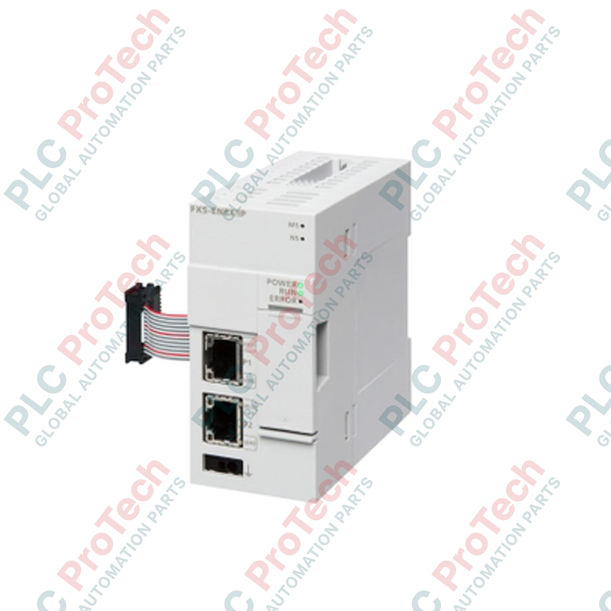
- Diagnostic LED array for real-time link status, module health, and network collision monitoring.
Applications
-
Multi-Vendor Integration: Connecting MELSEC iQ-F controllers to third-party EtherNet/IP compliant devices such as sensors and vision systems.
-
Distributed Field I/O: Managing remote I/O drops across large manufacturing footprints with minimal latency.
-
Drive Control: Real-time speed and torque command routing to compatible variable speed drives over industrial Ethernet.
-
SCADA and HMI Bridging: Serving high-throughput data to supervisor level control rooms and operator interfaces.
Technical Specifications
| Parameter |
Specification |
| Manufacturer |
Mitsubishi Electric |
| Model Number |
FX5-ENET/IP |
| Series |
MELSEC iQ-F Series |
| Module Type |
EtherNet/IP Network Module |
| Internal Power Supply |
24 V DC |
| Current Consumption |
110 mA |
| Transmission Rate |
100 Mbps / 10 Mbps (Auto-negotiation) |
| Communication Interface |
RJ45 Port (1 port) |
| Max. Cable Segment Length |
100 meters |
| Shipping Weight (Calculated) |
1.5 kg |
Status LED Configurations
| LED Indicator |
Operational State Meaning |
| RUN |
ON: Normal operation; OFF: Power off or hardware watchdog error. |
| ERR |
Flashing/ON: Hardware error or incorrect module parameter configuration. |
| NS (Network Status) |
Green (ON): Online connected; Red (Flashing): IP address conflict or connection timeout. |
| MS (Module Status) |
Green (ON): Module is operating normally; Red (ON): Unrecoverable hardware failure. |
Empirical Engineering Insights
Alternative Models & Compatibility
Unlike the built-in Ethernet port on FX5U CPU modules, which primarily processes CC-Link IE Field Basic, Modbus/TCP, and MELSOFT connection protocols, the FX5-ENET/IP is explicitly optimized for heavy-duty CIP (Common Industrial Protocol) traffic. If your network topology mandates cyclic, high-speed Class 1 implicit messaging with third-party components, this module must be appended. Note that firmware version 1.040 or higher in the host FX5 CPU is required for full feature exploitation.
Application Pitfalls & Engineering Notes
During high-traffic cyclic communication periods, network jitter can trigger NS fault codes. It is highly recommended to isolate EtherNet/IP messaging traffic from plant-wide IT office networks using managed switches with IGMP snooping configured. When mounting multiple extension modules, position the FX5-ENET/IP as close to the CPU as possible to ensure structural bus signaling integrity.
Commissioning & Wiring Tips
Always use Category 5e (or better) Double-Shielded Twisted Pair (S/FTP) cabling in high electromagnetic noise environments. Avoid routing the network cable parallel to high-voltage lines or variable frequency drive output cables to prevent induced noise from corrupting data packets.
Installation Guidelines
CRITICAL WARNING:
Ensure all AC and DC external power sources feeding the host PLC and associated field circuitry are completely de-energized before mounting, removing, or wiring the FX5-ENET/IP network module. Failure to do so can result in electrical shock, hardware failure, or unstable CPU bus behavior.
1
Align the module expansion connector with the right-side extension port of the host FX5 CPU or preceding expansion module.
2
Carefully press the module onto the DIN rail until the mounting hook clicks firmly into position. Secure the module extension joint latch.
3
Connect the system ground terminal to an isolated, low-impedance functional earth ground point. Do not share this ground path with high-current equipment.
4
Insert the shielded Ethernet RJ45 network plug into the communication port until it snaps securely. Power up the system and proceed with the hardware parameter mapping via GX Works3.