Description
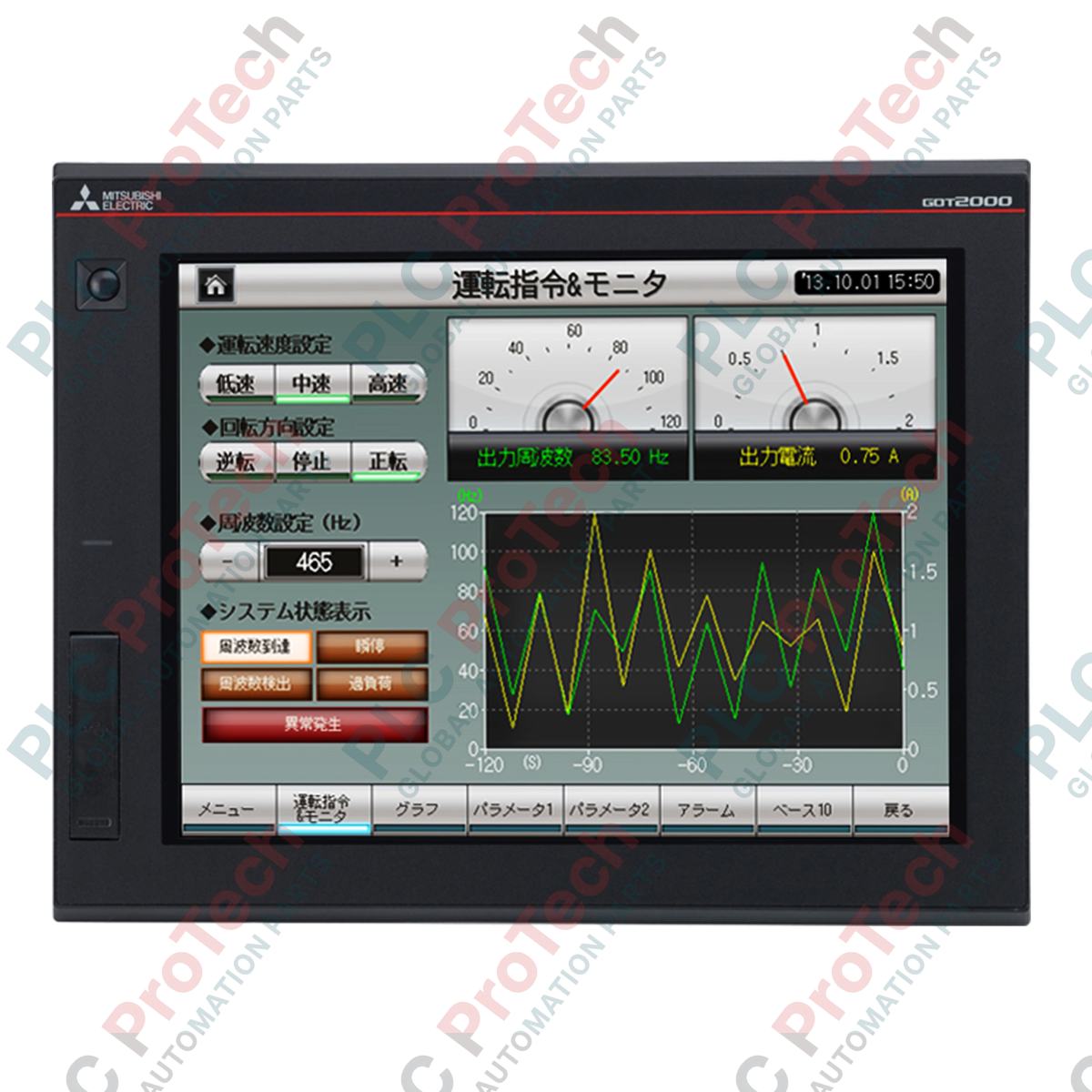
Direct visualization and multi-touch gestural control are fully integrated within the Mitsubishi Electric GT2712-STBA human-machine interface, an advanced terminal designed for high-performance automation environments. Operating as a core component of the GOT2000 GT27 platform, this graphical terminal features a 12.1-inch SVGA TFT display, supporting 65,536 colors with custom analog resistive multi-touch capabilities. A built-in human sensor automatically activates the screen backlight when an operator approaches within 1 meter, optimizing LED life and reducing overall energy consumption in heavy-duty control rooms.
Key Features
-
Multi-Touch Capability: Enables intuitive gestures such as pinching, zooming, and sweeping, up to 2 simultaneous points of interaction.
-
High-Resolution SVGA Display: 12.1-inch active matrix TFT screen with 800 x 600 resolution and adjustable 32-step brightness.
-
Intelligent Energy Saving: Built-in infrared pyroelectric sensor detects human proximity to toggle backlight sleep and wake modes automatically.
-
Robust Memory Configuration: Features 57 MB of storage memory (ROM) and 128 MB of operating memory (RAM) for complex graphic projects.
-
Diversified Connectivity: Built-in ports for high-speed Ethernet, RS-232, RS-422/485 serial communication, and USB host/device.
Applications
- High-speed automotive assembly line cell controllers.
- Precision chemical batching and processing visualization.
- Water and wastewater plant monitoring systems.
- Multi-axis machine tool automation interfaces.
Technical Specifications
| Specification Parameter |
Value / Detail |
| Manufacturer |
Mitsubishi Electric |
| Model Number |
GT2712-STBA |
| Display Size & Type |
12.1-inch TFT Color Liquid Crystal |
| Resolution |
SVGA (800 x 600 dots) |
| Supply Voltage |
100 to 240 V AC (+10%, -15%), 50/60 Hz |
| Power Consumption |
44 W or less (Maximum load) |
| Touch Panel Method |
Analog resistive type (2-point simultaneous touch) |
| Backlight Type |
LED (non-replaceable, lifetime approx. 60,000 hours) |
| Storage Memory (ROM) |
57 MB |
| Operating Memory (RAM) |
128 MB |
| Protection Structure |
Front panel: IP67F; Inside control panel: IP2X |
| Operating Temperature |
0 to 55 degC |
| Panel Cut Dimensions |
302 (W) x 228 (H) mm |
| Net Unit Weight |
2.4 kg |
| Shipping Weight (Calculated) |
10.0 kg (with full industrial protective packaging) |
| Package Dimensions (Calculated) |
380 mm x 310 mm x 120 mm |
Connections and Interfaces
| Interface Type |
Connector / Format |
Transmission Specifications |
| Ethernet Channel |
RJ-45 (1 ch) |
10BASE-T / 100BASE-TX automatic negotiation |
| RS-232 Channel |
D-Sub 9-pin Male (1 ch) |
Up to 115200 bps transmission speed |
| RS-422/485 Channel |
D-Sub 9-pin Female (1 ch) |
Up to 115200 bps transmission speed |
| USB Host |
USB-A (2 ch - 1 front, 1 rear) |
USB 2.0 High-Speed 480 Mbps |
| USB Device |
USB Mini-B (1 ch - front) |
PC connection for project download/debugging |
| Storage Card Slot |
SD Memory Card (1 ch) |
SDHC compliant, up to 32 GB supported |
Empirical Engineering Insights
Alternative Models & Compatibility
The GT2712-STBA serves as a drop-in panel replacement for older GT1675 and GT1575 12.1-inch SVGA terminals. While the physical panel cutout remains identical at 302 mm x 228 mm, the newer screen features a slimmer depth of 52 mm, leaving more clearance inside the cabinet. Project screen files developed in GT Designer2 or early GT Designer3 versions must be converted and compiled under GT Works3 version 1.100V or higher to properly scale assets and map functions to multi-touch interfaces.
Application Pitfalls & Engineering Notes
When deploying the unit in high-temperature settings or close to direct heating sources, the onboard sensor may experience thermal blind spots. If the delta between ambient temperature and human skin falls below 4 degC, the wake-up proximity function degrades. For consistently hot environments, it is recommended to bypass sensor sleep states in software and set a localized timer-based screen dimming register to maintain screen longevity without relying on proximity detection.
Commissioning & Wiring Tips
To prevent grounding-loop interference on the multi-touch panel capacitive matrix, ensure a Class D ground (resistance of 100 ohms or less) is established via the dedicated M3 ground stud. Do not share the grounding run with high-current variable frequency drives (VFDs) or motor controls. When using RS-422 communications, keep cable distances under 500 meters and use shielded twisted-pair cabling to preserve high-speed communication packet integrity.
Installation Guidelines
CRITICAL SAFETY WARNING
Isolate and lock out all AC power systems feeding the enclosure before beginning panel cutting or terminal wiring. Dangerous AC voltages up to 240 V are present at the power block terminal. Allow a minimum of 5 minutes for internal filter capacitors to discharge completely prior to working on internal physical hardware connections.
1
Perform a clean rectangular panel cutout of 302 mm x 228 mm (tolerance +1.0 mm, -0 mm) in the enclosure door. Ensure the mounting panel is flat within 2 mm or less to prevent physical torsion on the HMI housing.
2
Inspect the continuous rubber water-resistant gasket around the perimeter bezel. Slide the terminal into the cutout opening from the front of the enclosure.
3
Insert the provided mounting fixtures into the matching slot tracks on the sides of the terminal. Tighten the mounting screws in a diagonal sequence using a torque rating of 0.20 to 0.25 N-m to ensure uniform compression and maintain the front IP67F seal rating.
4
Connect external source AC power wires (0.75 to 2 mm2) to the M3 screw terminals of the power supply card. Tighten the power terminal screws to a torque of 0.5 to 0.8 N-m, ensuring correct phase, neutral, and ground routing.