Description
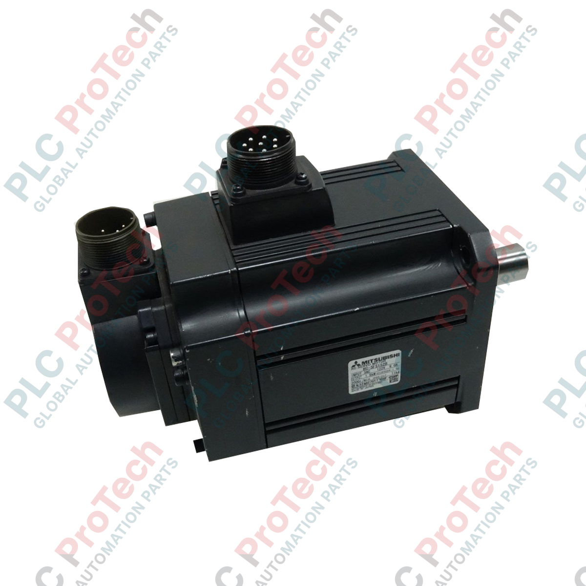
Delivering high-torque drive capabilities to heavy-duty industrial machinery, the Mitsubishi Electric HC-SFS702BG1H 1/11 is a high-capacity, medium-inertia industrial servo motor. This unit integrates a powerful 7.0 kW motor with a built-in electromagnetic safety brake and a specialized G1H leg-type reduction gear featuring a 1/11 reduction ratio. Designed for applications requiring precise speed regulation and reliable torque multiplication, this robust motor ensures exceptional dynamic response and stable operation under heavy load variations.
Key Features
-
High Capacity Output: Rated at 7.0 kW, providing massive rotational power for heavy machinery.
-
Integrated G1H Reduction Gear: Precision leg-mounted reducer with a 1/11 ratio optimized for heavy industrial applications.
-
Electromagnetic Holding Brake: Built-in safety brake ensures instant axis locking and secure load retention during power-off conditions.
-
Medium Inertia Design: Ideal for applications with fluctuating loads, ensuring stable control loop performance.
-
Rugged Cast Frame: High torsional stiffness and excellent thermal dissipation properties for continuous duty cycles.
Industrial Applications
- Heavy metal forming, stamping, and cutting machinery.
- High-capacity material handling and gantry conveyor systems.
- Industrial mixing, compounding, and extrusion systems.
- Paper milling, winding, and high-tension web-handling lines.
Technical Specifications
| Parameter |
Specification Value |
| Manufacturer |
Mitsubishi Electric |
| Model Number |
HC-SFS702BG1H 1/11 |
| Motor Series |
HC-SFS |
| Rated Output |
7.0 kW |
| Rated Speed |
2000 r/min |
| Inertia Type |
Medium Inertia |
| Electromagnetic Brake |
Integrated Holding Brake |
| Reduction Gear Type |
G1H (General industrial machine, leg-type) |
| Reduction Ratio |
1/11 |
| Country of Origin |
Japan |
| Shipping Weight |
146 kg |
Connections and Interfaces
| Connection / Terminal |
Functional Assignment |
| Motor Power U / V / W |
3-Phase AC motor power lines from servo amplifier |
| PE (Ground) |
Protective earth grounding terminal |
| Encoder Connector |
High-resolution serial absolute feedback interface |
| B1 / B2 |
24V DC Electromagnetic Brake power terminals (Polarity-free) |
Empirical Engineering Insights
Alternative Models & Compatibility
When pairing this motor with Mitsubishi servo drives, ensure that the drive parameters are explicitly updated to reflect the 1/11 physical gear reduction. Failure to configure the electronic gear ratio correctly in the parameters will cause mismatch faults between command pulses and actual axis movement. For legacy systems, verify that your servo amplifier firmware fully supports the HC-SFS high-resolution feedback protocols.
Application Pitfalls & Engineering Notes
Due to the massive 146 kg weight and heavy-duty torque multiplication of the G1H reduction unit, rigid mounting is mandatory. Mount this motor on a machined, stress-relieved steel baseplate to prevent vibration-induced shaft misalignment. Thermal expansion of the leg-mount gear casing under high continuous duty cycles must be accounted for to preserve alignment tolerances over time.
Commissioning & Wiring Tips
Always implement a dedicated external surge suppressor (diode or varistor) across the 24V DC electromagnetic brake power lines. The inductive kickback from releasing this heavy holding brake can otherwise inject high-frequency noise into the encoder's feedback run, leading to intermittent feedback errors. Route motor power and feedback cables in separate, shielded trays to minimize EMI.
Installation Guidelines
CRITICAL WARNING: Prior to installation, ensure the primary 3-phase power supply to the servo drive is completely de-energized and locked out. Allow a minimum of 20 minutes for the internal capacitors to fully discharge. Verify zero voltage at the drive output terminals with a calibrated multimeter before proceeding with wiring.
1
Mechanically align and secure the leg-type mounting frame to the machine bed using high-tensile strength bolts torqued to the manufacturer specification.
2
Connect the protective earth (PE) ground terminal directly to the central electrical panel grounding busbar to prevent noise and grounding loops.
3
Wire the 3-phase power phases (U, V, W) using shielded motor cables, ensuring correct phase sequence alignment to prevent unexpected motor reversal.
4
Plug in the high-resolution feedback encoder and connect the 24V DC safety holding brake lead wires to their respective drive-controlled relay outputs.