Description
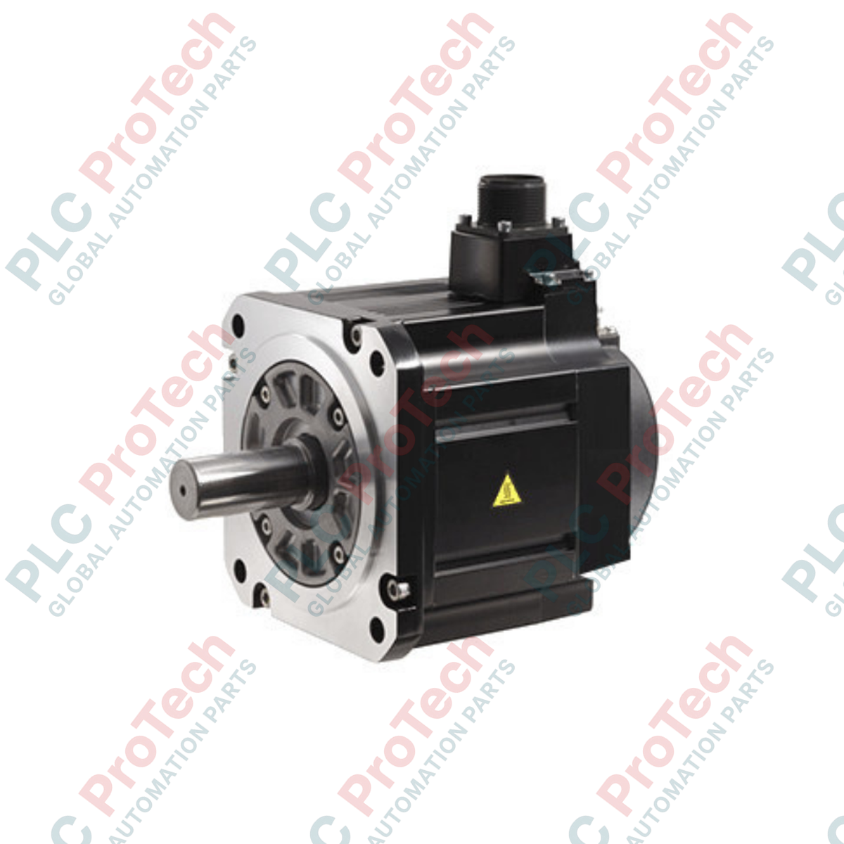
Operating as a high-capacity rotary motion component within industrial drive systems, this Mitsubishi Electric HG-SN302BJ-S100 unit delivers 3.0 kW of rated output power for precision speed and torque applications. Engineered for integration with compatible MELSERVO servo amplifiers, the motor features an integrated electromagnetic brake designed to hold loads securely during power-off states, alongside a factory-installed oil seal to prevent fluid ingress along the shaft line. Its robust physical architecture offers a totally enclosed, natural cooling design rated to IP67 standards, making it highly suitable for challenging factory floor environments requiring resilience against moisture and particulate contamination.
Features
-
Electromagnetic Braking: Built-in safety-holding brake prevents axis drift or vertical drop in the event of power loss.
-
Enhanced Environmental Sealing: Equipped with an integrated oil seal and built to IP67 enclosure specifications for protection against dust and liquid ingress.
-
Low-Inertia Performance: Tailored for rapid acceleration and deceleration profiles with a recommended load-to-motor inertia ratio of 15 times or less.
-
Industrial-Grade Thermal Limit: Class 155 (F) insulation rating ensures optimal thermal margin and reliability during continuous operations.
-
High Vibration Resistance: Robust frame structure qualified for vibration resistance of 24.5 m/s2 along the X-axis and 49 m/s2 along the Y-axis.
Applications
-
Vertical Axis Controls: Ideal for gantry systems, hoists, and Z-axis ball screw positioning where an electromagnetic holding brake is operationally critical.
-
Packaging and Material Handling: Drive system for high-speed indexing tables, continuous feed systems, and conveyor line automation.
-
Machine Tool Feeding: Delivers precise, high-torque feed motions under varying load profiles.
-
Heavy Manufacturing Environments: Deployed in settings prone to coolant spray, oil mist, and dust accumulation.
Technical Specifications Table
| Parameter |
Value / Specification |
| Manufacturer |
Mitsubishi Electric |
| Model Number |
HG-SN302BJ-S100 |
| Series Type |
HG-SN Series |
| Rated Output |
3.0 kW |
| Rated Speed |
2000 r/min |
| Maximum Speed |
2500 r/min |
| Instantaneous Permissible Speed |
2875 r/min |
| Rated Torque |
14.3 N-m |
| Rated Current |
11 A |
| Maximum Current |
33 A |
| Power Rate at Continuous Rated Torque |
23.3 kW/s |
| Insulation Class |
155 (F) |
| Enclosure Rating |
IP67 (Totally enclosed, natural cooling) |
| Electromagnetic Brake |
Integrated (Holding type) |
| Oil Seal |
Installed |
| Operating Temperature Range |
0 to 40 degC (non-freezing) |
| Storage Temperature Range |
-15 to 70 degC (non-freezing) |
| Vibration Resistance |
X: 24.5 m/s2, Y: 49 m/s2 |
| Country of Origin |
Japan |
| Net Motor Weight |
22.0 kg |
| Shipping Weight (Calculated) |
23.0 kg |
| Package Dimensions (Calculated) |
480 x 300 x 300 mm |
Empirical Engineering Insights
Alternative Models & Compatibility
The HG-SN302BJ-S100 is designed to operate seamlessly with standard MR-JE servo amplifier architectures. Note that the "B" and "J" designations (Brake and Oil Seal respectively) alter the physical dimensions and moment of inertia compared to standard HG-SN302 units. Always verify amplifier firmware parameters match the exact model configuration to ensure correct current limits and feedback loop tuning are initiated upon first startup.
Application Pitfalls & Engineering Notes
The electromagnetic brake installed in this motor is strictly for holding static positions and must never be applied to decelerate a moving dynamic load. Engaging the brake during rotation will cause severe friction disc wear, reduction in holding torque, and premature brake failure. Additionally, ensure the oil seal is regularly inspected in wet environments, as running the motor with a dry or damaged seal can lead to shaft damage or liquid migration into the internal encoder housing.
Commissioning & Wiring Tips
Always route the high-voltage motor power cables and the low-voltage encoder/feedback lines in separate, shielded cable conduits to prevent electromagnetic interference (EMI). Ground the motor chassis directly to the main system panel ground plate using a heavy, low-impedance braided strap. When wiring the brake line, ensure a surge protection diode or varistor is installed across the brake coil terminals to suppress voltage spikes during coil de-energization.
Installation Guidelines
CRITICAL WARNING
Before performing any installation, maintenance, or physical inspection, ensure that all upstream electrical sources are locked and tagged out in accordance with standard industrial safety procedures. Wait a minimum of 15 minutes after power-down to allow the internal DC bus capacitors of the connected servo amplifier to discharge completely. Verify zero voltage at the drive terminals before handling motor connections.
1
Mechanical Alignment: Mount the motor on a rigid, flat metal plate that can act as an effective heat sink. Carefully align the motor shaft with the driven load; misalignment exceeding tolerance limits will accelerate bearing wear and can lead to shaft breakage.
2
Shielded Cable Routing: Connect the dedicated motor power and encoder cables. Keep the encoder cable isolated from power cables by a distance of at least 30 cm (12 inches) to minimize cross-talk and prevent encoder signal faults.
3
Brake Control Integration: Connect the electromagnetic brake control circuit to an external 24V DC auxiliary power supply. Integrate the brake control relay sequence into the drive's safety/fault loop so that the brake engages instantly if a drive fault is triggered.