Description
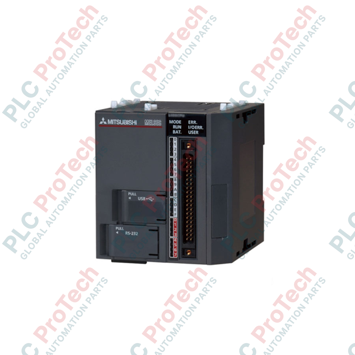
Optimizing compact control architectures with high-speed execution, the Mitsubishi Electric L06CPU-P serves as a highly capable central processing unit within the rack-free MELSEC L Series family. This controller integrates built-in digital inputs and outputs directly on the CPU body, configured specifically for PNP (source) switching logic. Designed with a program capacity of 240K bytes (approximately 60K steps), it manages sophisticated control tasks while offering onboard Ethernet, USB, and SD/SDHC card interfaces. The module eliminates the physical constraints of traditional backplanes, mounting directly to a standard DIN rail and connecting via lateral bus connectors for modular expansion.
Features
-
PNP Output Configuration: Integrated 24-point I/O block featuring 16 digital inputs and 8 transistor outputs utilizing source (PNP) logic.
-
Onboard Communications: Dedicated RJ45 Ethernet port supporting MC Protocol and Modbus/TCP, paired with a Mini-USB port for programming.
-
Flexible Data Storage: Integrated SD/SDHC memory card slot for data logging, firmware updates, and comprehensive parameter backup.
-
High-Speed Processing: Achieves basic instruction execution times of 9.5 ns for sequence instructions, ensuring fast program scans.
-
Rack-Free Modular Design: Direct-mount DIN-rail installation with side-by-side connector coupling simplifies cabinet layouts.
Applications
-
Packaging Machinery: Executing registration control, high-speed counting, and positioning profiles on compact packaging lines.
-
Conveyor and Material Handling: Localized routing, sorting, and lifter controls utilizing integrated PNP sensor networks.
-
Water Treatment Subsystems: Standalone pump station controllers requiring native Ethernet communications and compact foot-prints.
Technical Specifications
| Parameter |
Value |
| Manufacturer |
Mitsubishi Electric |
| Model Number |
L06CPU-P |
| Control Series |
MELSEC L Series |
| Program Memory |
240K bytes (60K steps) |
| Standard RAM |
768K bytes |
| Standard ROM |
1024K bytes |
| Built-In I/O Points |
24 points total (16 Inputs / 8 Outputs) |
| Output Switching Logic |
Transistor (Source / PNP) |
| Basic Processing Speed |
9.5 ns (LD Instruction) |
| Internal Current Consumption (5 VDC) |
0.65 A |
| Operating Temperature Range |
0 to 55 degC |
| Shipping Weight (Calculated) |
3.0 kg (with protective packaging) |
| Unit Dimensions |
90 mm x 28.5 mm x 95 mm |
Connections and Interfaces
| Interface / Connection |
Technical Assignment |
| RJ45 Ethernet Port |
10BASE-T/100BASE-TX communication (MC Protocol, TCP/IP, UDP) |
| USB Port |
Mini-B female connector for high-speed GX Works2 programming link |
| Built-In I/O Connector |
40-pin high-density connector for 24 VDC PNP digital input/output wiring |
| SD Card Slot |
Supports standard SD and SDHC memory cards up to 32 GB |
Alternative Models & Compatibility
The L06CPU-P is the source-type counterpart to the standard L06CPU, which relies on sink (NPN) transistor outputs. Substituting one for the other requires careful verification of field sensor wiring and polarity. If scaling program parameters or requiring larger data tables, consider migrating to the L26CPU-P, which doubles step execution capabilities while remaining completely compatible with the same lateral extension bus modules.
Application Pitfalls & Engineering Notes
When utilizing the integrated high-speed counters built into the I/O block, ensure the signal rise and fall times do not exceed the configured response filter. High electrical noise in proximity to the I/O cables can cause miscounts. Always route I/O lines separate from high-voltage AC cables. In fully enclosed control panels with limited air circulation, note that continuous high-speed switching across all 8 output channels simultaneously can raise module temperature; verify that panel ambient temperatures remain below 55 degC.
Commissioning & Wiring Tips
To communicate with the CPU over Ethernet, ensure the programming laptop resides on the same subnet as the default CPU IP address or utilize the direct-connection search tool within GX Works2. When terminating the 40-pin I/O connector, apply a separate, regulated external 24 VDC power supply to the designated common terminals to isolate the CPU backplane logic from potential field wiring short-circuits.
Installation Guidelines
CRITICAL WARNING: Ensure all external AC and DC power supplies feed-into the panel are completely de-energized before mounting, removing, or wiring the CPU module. Failing to isolate power can cause immediate permanent damage to the CPU's internal ASIC communication layer and risk personal safety.
1
Align the CPU module on the standard 35 mm DIN rail, then push the unit firmly until the lower locking tab clicks into place.
2
Slide the expansion bus connector cover sideways and attach the neighboring power supply module or expansion unit, ensuring the connector locks engage completely.
3
Connect the functional ground terminal of the adjacent power supply module to the central cabinet ground bus using a short, low-impedance conductor.