Description
Regulating heavy-duty dynamic motion profiles within complex automation lines, the Mitsubishi Electric MR-H700AN is a high-capacity AC servo amplifier engineered for precision control. This unit delivers a robust 7 kW rated output to match demanding industrial requirements, operating within the legacy MR-H series ecosystem. The drive utilizes advanced sine-wave PWM control to ensure smooth torque distribution and high-accuracy positioning for compatible servo motors. Designed for general-purpose industrial positioning, it provides reliable operational feedback, integrated protective diagnostics, and a rugged frame designed to withstand harsh factory environments.
Features
-
High Power Output: Full 7 kW output capacity designed to drive high-inertia motors in heavy positioning configurations.
-
Precise Control Algorithm: Sine-wave PWM current control system optimizes motor efficiency and reduces torque ripple.
-
Comprehensive Diagnostics: Built-in detection for overcurrent, regenerative overvoltage, overload, and encoder feedback faults.
-
Rugged Enclosure: Industrial-grade housing with efficient forced-air cooling fans for stable thermal performance.
Applications
- Heavy-duty gantry systems and automated material handling.
- Industrial metalworking, CNC machining axes, and forming presses.
- Large-scale packaging machinery and indexing tables.
- Tension control systems in paper, foil, and textile converting lines.
Technical Specifications
| Parameter |
Value / Specification |
| Manufacturer |
Mitsubishi Electric |
| Model Number |
MR-H700AN |
| Series |
MR-H Series |
| Rated Output Capacity |
7.0 kW |
| Control Method |
Sine-wave PWM control / current control system |
| Cooling System |
Forced-air cooling fan (integrated) |
| Operating Temperature |
0 to 55 degC (non-freezing) |
| Storage Temperature |
-20 to 65 degC (non-freezing) |
| Shipping Weight |
14.0 kg |
| Package Dimensions (Calculated) |
460 mm x 320 mm x 340 mm |
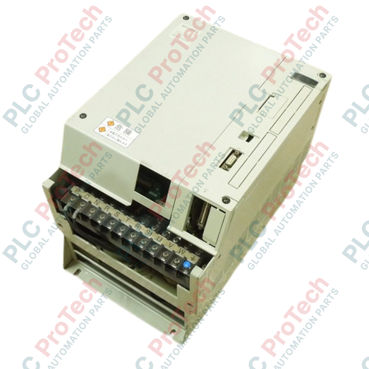
Connections and Interfaces
| Terminal / Port |
Functional Assignment |
| L1, L2, L3 |
Main circuit 3-phase AC input terminals |
| U, V, W |
Servo motor power output connections |
| CN1 (A/B) |
I/O control signal interfaces for external command linking |
| CN2 |
Feedback encoder connection interface |
Alternative Models & Compatibility
The MR-H series is a legacy motion control platform. Direct drop-in compatibility with modern MR-J4 or MR-J5 series requires physical footprint modification and motor replacement, as newer systems utilize high-resolution serial absolute encoders which are protocol-incompatible with legacy MR-H feedback configurations. When replacing a unit within an existing network, maintain identical parameter maps to preserve system timing and synchronization variables.
Application Pitfalls & Engineering Notes
Thermal management is the most critical variable when deploying 7 kW amplifiers. In closed cabinets, failure to maintain a minimum clearance of 40 mm above and below the housing can lead to rapid heat pooling and premature activation of thermal safety limits. If persistent regeneration errors (such as AL.30 or AL.33) occur during rapid deceleration phases, evaluate the impedance of the external regenerative discharge resistor to ensure correct energy dissipation.
Commissioning & Wiring Tips
Always run the encoder feedback cable (CN2) separately from the high-voltage motor output lines (U, V, W) to prevent signal degradation from electromagnetic interference (EMI). Ground the amplifier chassis securely using a low-impedance copper wire with a cross-section of at least 8 mm2 directly to the primary panel ground bus. Terminal screw torque settings must be monitored periodically under high-vibration operating conditions to prevent localized resistive heating.
Installation Guidelines
CRITICAL WARNING
Disconnect all primary AC electrical feeds before attempting mounting, wiring, or maintenance. Allow at least 15 minutes post-power-off for internal capacitors to fully discharge. Always verify that the DC bus voltage across the power terminals is below 20V using a calibrated digital voltmeter before touching physical terminals.
1
Mount the amplifier vertically against a rigid, conductive metal panel to maximize thermal dissipation and establish a robust ground reference path.
2
Connect the dedicated ground terminal first to eliminate risk of electrostatic discharge damage during control wiring configuration.
3
Connect the encoder cable (CN2) and I/O interface logic cabling, keeping control paths physically isolated from heavy electrical cables.
4
Wire the main three-phase power supply inputs (L1/L2/L3) and execute final connection checks before applying power.