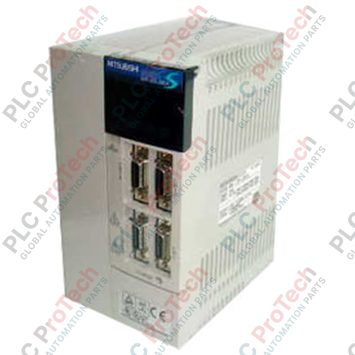
Description
Managing precise multi-axis motion profiles within automated industrial lines, the Mitsubishi Electric MR-J2S-200B servo amplifier delivers high-performance closed-loop AC servo control. This unit communicates natively via the high-speed SSCNET synchronous network, enabling synchronous control with minimal wiring complexity. Built for industrial dependability, it features advanced real-time adaptive auto-tuning that adjusts control gains dynamically to match shifting mechanical loads. Designed with an integrated dynamic brake and comprehensive protection loops, it maintains optimal torque and velocity tracking under demanding industrial operating conditions.
Key Features
-
SSCNET Serial Bus Integration: Uses high-speed serial communications to minimize wiring and reduce noise susceptibility in complex multi-axis motion configurations.
-
Real-Time Adaptive Tuning: Automatically calculates load inertia ratio and continuously optimizes control parameters for stable operation.
-
Comprehensive Safety and Diagnostics: Features dedicated hardware watchdogs for overcurrent, overvoltage, motor overheating, and encoder communication faults.
-
Robust Thermal Management: Fitted with an integrated fan cooling system to ensure continuous operation in high-density control cabinets.
Applications
- High-speed pick-and-place robotic systems and assembly automation.
- Multi-axis packaging machines, indexing tables, and material handling systems.
- Precision CNC machine tools, grinding centers, and printing machinery.
- Semiconductor fabrication systems demanding highly repeatable positioning.
Technical Specifications
| Specification Parameter |
Value |
| Manufacturer |
Mitsubishi Electric |
| Model Series |
MELSERVO J2-Super (MR-J2S) |
| Control Architecture |
Sinusoidal PWM control/current control system |
| Rated Capacity |
2.0 kW |
| Input Power Supply |
3-phase 200-230 VAC, 50/60 Hz |
| Permissible Voltage Fluctuation |
3-phase 170-253 VAC |
| Permissible Frequency Fluctuation |
+/- 5% |
| Communication Protocol |
SSCNET High-Speed Serial Bus (5.6 Mbps) |
| Speed Frequency Response |
550 Hz or more |
| Dynamic Brake |
Built-in |
| Enclosure Rating |
IP00 (Open structure, forced air fan-cooling) |
| Operating Ambient Temperature |
0 to 55 degC (no freezing) |
| Operating Humidity |
90% RH maximum (non-condensing) |
| Maximum Operational Elevation |
1000m or less above sea level |
| Vibration Resistance |
5.9 m/s2 maximum |
| Country of Origin |
Japan |
| Shipping Weight (Calculated) |
2.5 kg |
Connections and Interfaces
| Terminal / Connector Reference |
Functional Description |
| L1, L2, L3 |
Main circuit 3-phase AC power input |
| L11, L21 |
Control circuit single-phase AC power input |
| U, V, W |
Servo motor power output phase connections |
| P, C, Cr |
Regenerative option terminals (short-circuit bar across P and Cr for standard built-in resistor) |
| CN1A |
SSCNET communication input connector (from master motion controller or previous axis) |
| CN1B |
SSCNET communication output connector (daisy-chain to subsequent axis) |
| CN2 |
Servo motor high-resolution encoder feedback interface |
| CN3 |
Personal computer/parameter unit configuration port |
Empirical Engineering Insights
Alternative Models & Compatibility
The MR-J2S-200B is configured specifically for SSCNET network installations. If you are retrofitting or replacing an analog or pulse-train model, the correct replacement is the MR-J2S-200A. Migrating legacy MELSERVO-J2S setups to modern MELSERVO-J4 series drives will require the use of a dedicated SSCNET to SSCNET III/H converter gateway or a full system redesign since the legacy 5.6 Mbps SSCNET protocol is physically and electrically incompatible with modern fiber-optic networks.
Application Pitfalls & Engineering Notes
When packing amplifiers tightly in sealed cabinets, pay close attention to thermal dissipation. Provide a minimum clearance of 40 mm above and below the amplifier, and at least 10 mm on either side when using multi-unit mounting patterns. High duty-cycle acceleration/deceleration steps can lead to a regenerative overvoltage fault (AL.30 or AL.50). Ensure that if an external regenerative resistor is installed, the short-circuit bar across P and Cr is fully removed, and the alternative parameter group is updated to prevent severe damage to the internal power transistors.
Commissioning & Wiring Tips
Always route the high-voltage motor output lines (U, V, W) in a separate run from the CN2 encoder feed and control signaling lines. Induced EMI noise on the encoder feedback line can generate intermittent communication packet errors, triggering an AL.16 or AL.20 fault code. Utilize braided shielding for the motor cable, with 360-degree clamp grounding directly at the metal backplate of the electrical enclosure.
Installation Guidelines
CRITICAL WARNING: Hazardous voltages remain present inside the amplifier's DC bus capacitors for several minutes after input AC power is disconnected. Always verify with a digital multimeter that the DC bus terminal voltage is below 50 VDC before initiating any physical terminal inspection or wiring modification.
1
Securely mount the servo amplifier vertically on a flat, vibration-free steel backplate using the provided installation eyelets to allow optimum upward airflow.
2
Connect control circuit terminals L11 and L21 to the control AC bus, keeping control logic energized even if the main three-phase supply is tripped.
3
Ensure terminal block connection integrity by torquing primary electrical terminals (L1/L2/L3, U/V/W) to their rated values to prevent local hot spots under load.