Description
Engineered for precise speed, torque, and position control in heavy industrial environments, the Mitsubishi Electric MR-J3-500A4 is a high-performance digital servo amplifier belonging to the MELSERVO MR-J3 product family. This unit operates on a 400V class grid and is optimized for managing brushless servo motors with continuous current requirements of up to 14.0 A. Incorporating advanced real-time auto-tuning and vibration suppression filters, this amplifier ensures high response levels while suppressing mechanical resonance on critical axes.
Key Features
-
Dual-Loop Feedback Control: Supports highly accurate position loops by processing high-resolution encoder signals.
-
Built-In Dynamic Brake: Integrated hardware dynamic braking circuit allows for rapid and safe motor deceleration under emergency stop conditions.
-
Robust Thermal Management: Force-cooling design featuring integrated fan units maintains optimum temperatures during intensive duty cycles.
-
High-Voltage Tolerance: Main power supply supports input ranges up to 480VAC to integrate with global power distribution systems.
Applications
-
CNC Machine Tools: High-torque multi-axis machining and turning centers.
-
Packaging & Assembly: Fast-acting, synchronized product packaging machinery and multi-stage assembly lines.
-
Material Handling Systems: Dynamic positioning overhead gantry cranes, high-payload robotic loaders, and conveyor sorting lines.
Technical Specifications
| Parameter |
Technical Specification |
| Manufacturer |
Mitsubishi Electric |
| Model Code |
MR-J3-500A4 |
| Product Series |
MELSERVO MR-J3 Series |
| Main Circuit Power Supply |
3-phase 380 to 480 VAC, 50/60 Hz |
| Permissible Voltage Fluctuation |
3-phase 323 to 528 VAC |
| Main Circuit Rated Current |
10.8 A |
| Control Circuit Power Supply |
1-phase 380 to 480 VAC, 50/60 Hz |
| Control Circuit Rated Current |
0.2 A |
| Control Circuit Power Consumption |
45 W |
| Rated Output Voltage |
3-phase 323 VAC |
| Rated Output Current |
14.0 A |
| Dynamic Brake |
Built-in |
| Cooling System |
Force-cooling (integrated cooling fan) |
| Net Weight |
4.6 kg |
| Shipping Weight (Calculated) |
6.0 kg |
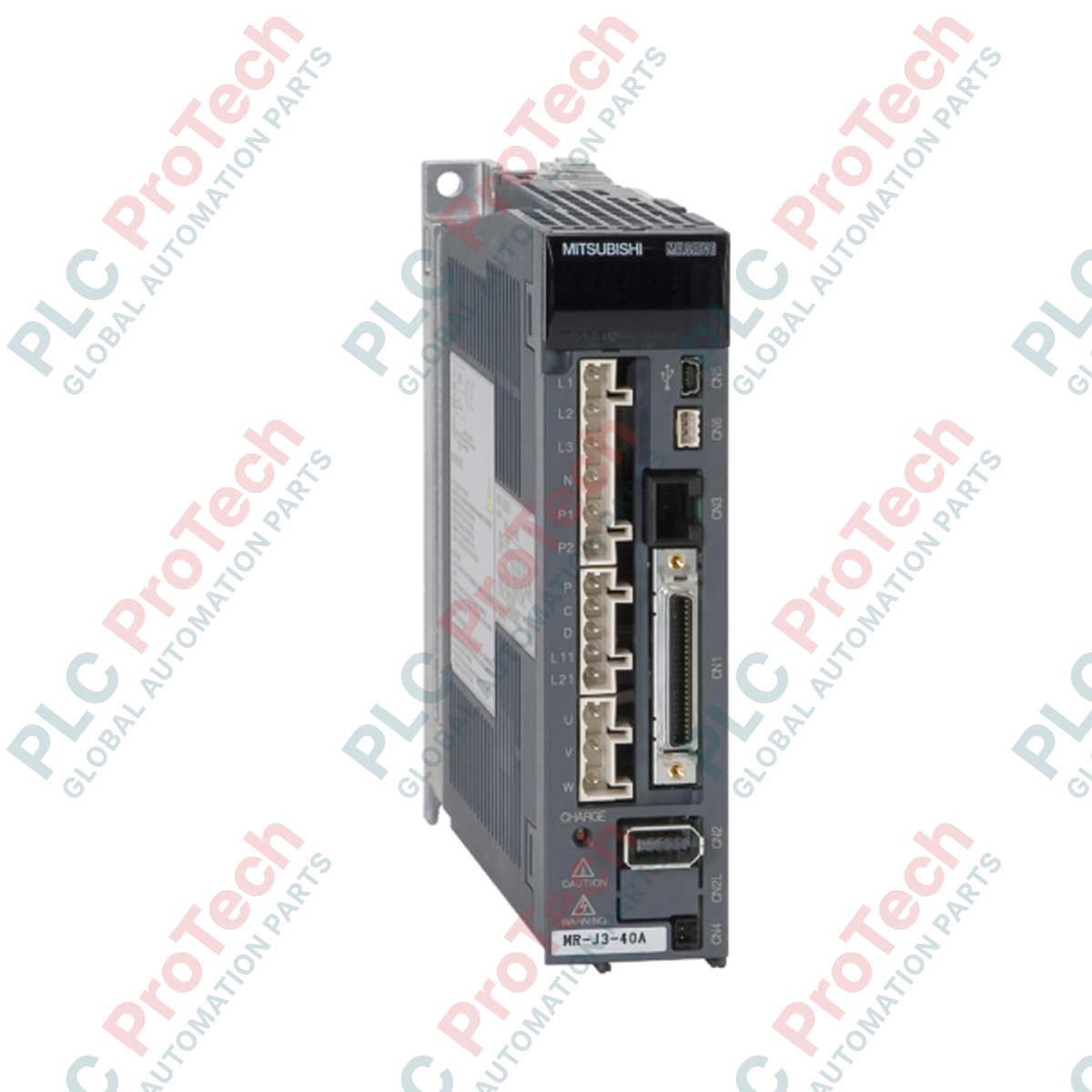
Connections and Interfaces
| Terminal / Connector |
Function / Circuit Assignment |
| L1, L2, L3 |
Main circuit 3-phase AC power input |
| L11, L21 |
Control circuit 1-phase AC power input |
| U, V, W |
Servo motor power output terminals |
| CN1 |
General-purpose analog / pulse train I/O interface |
| CN2 |
High-resolution encoder feedback input |
| CN3 |
PC connection or parameter setup unit interface |
Empirical Engineering Insights
Alternative Models & Compatibility
The MR-J3-500A4 is the general-purpose, non-networked analog/pulse-train variant within the MR-J3 400V series. Please note that it cannot directly replace the MR-J3-500B4, which is built exclusively for the SSCNET III optical fiber network. Ensure controller-side interface compatibility before deployment.
Application Pitfalls & Engineering Notes
Due to the high thermal dissipation profile under continuous heavy load conditions, cabinet designers must ensure a minimum of 40 mm vertical clearing space above and below the amplifier. If installing multiple amplifiers adjacently in an enclosed panel, maintain an ambient operating temperature below 55 degC to prevent premature overtemperature trips.
Commissioning & Wiring Tips
To prevent high-frequency electro-magnetic interference (EMI) originating from the PWM inverter output, ensure the motor feed cables are properly shielded and grounded to the common baseplate. Additionally, control line cabling on the CN1 connector must use shielded, twisted-pair lines separated from the primary high-power wiring.
Installation Guidelines
CRITICAL WARNING
Before beginning installation, service, or wiring procedures, isolate and de-energize all primary input and control voltages. Wait a minimum of 15 minutes to allow internal high-voltage DC bus capacitors to discharge to a safe level. Verify with a calibrated multimeter that DC bus voltage is zero before making physical terminal contacts.
1
Mount the servo amplifier vertically on a flat, non-flammable surface inside a dust-free and moisture-free control enclosure.
2
Connect the safety protective earth (PE) ground terminal of the amplifier directly to the main system electrical ground point.
3
Wire the main 3-phase AC input supply lines to terminals L1, L2, and L3, then wire the separate single-phase control supply lines to terminals L11 and L21.
4
Verify the secure insertion of encoder connector feedback line CN2 and analog/digital command harness CN1 before powering on.