Description
Designed to execute high-precision motion profiles within the MELSERVO-J3 system architecture, the Mitsubishi Electric MR-J3-60B AC servo amplifier offers high-speed control loops and synchronized multi-axis coordination. Equipped with a digital SSCNET III fiber-optic communication interface, this drive integrates directly into complex industrial automation configurations to minimize latency and ensure noise-free signal transmission. It operates with high-resolution feedback systems to guarantee positioning accuracy, making it ideal for processes requiring tight speed constancy and dynamic performance.
Features
-
SSCNET III Bus Interface: High-speed, noise-immune synchronous optical fiber network communication for precise multi-axis positioning and coordination.
-
High-Resolution Feedback compatibility: Seamless processing of 18-bit absolute/incremental encoder signals providing 262,144 pulses per revolution.
-
Adaptive Vibration Suppression: Advanced filtration system designed to minimize mechanical resonance and structural oscillations during rapid deceleration or acceleration.
-
Real-Time Auto Tuning: Automatic adjustment of gain settings to optimize response according to the real-time load inertia ratio.
-
Integrated Diagnostic Port: Direct USB connection for configuration, monitoring, and trend analysis using MR Configurator software.
Applications
- Multi-axis CNC milling, routing, and precision grinding machines.
- Pick-and-place robots and electronic component assembly systems.
- High-speed packaging, filling, and continuous labeling machinery.
- Semiconductor handling machinery and wafer positioning systems.
Technical Specifications
| Parameter |
Value |
| Manufacturer |
Mitsubishi Electric |
| Model Number |
MR-J3-60B |
| Series |
MELSERVO-J3 |
| Rated Output Capacity |
0.6 kW (600W) |
| Main Circuit Power Supply |
3-phase or 1-phase 200 to 230 VAC, 50/60 Hz |
| Control Circuit Power Supply |
1-phase 200 to 230 VAC, 50/60 Hz |
| Communication Interface |
SSCNET III (High-speed synchronous network) |
| Control Method |
Sine-wave PWM control / Current control system |
| Ambient Operating Temperature |
0 to 55 degC (non-freezing) |
| Dynamic Brake |
Built-in |
| Cooling Method |
Natural cooling |
| Shipping Weight (Calculated) |
2.1 kg |
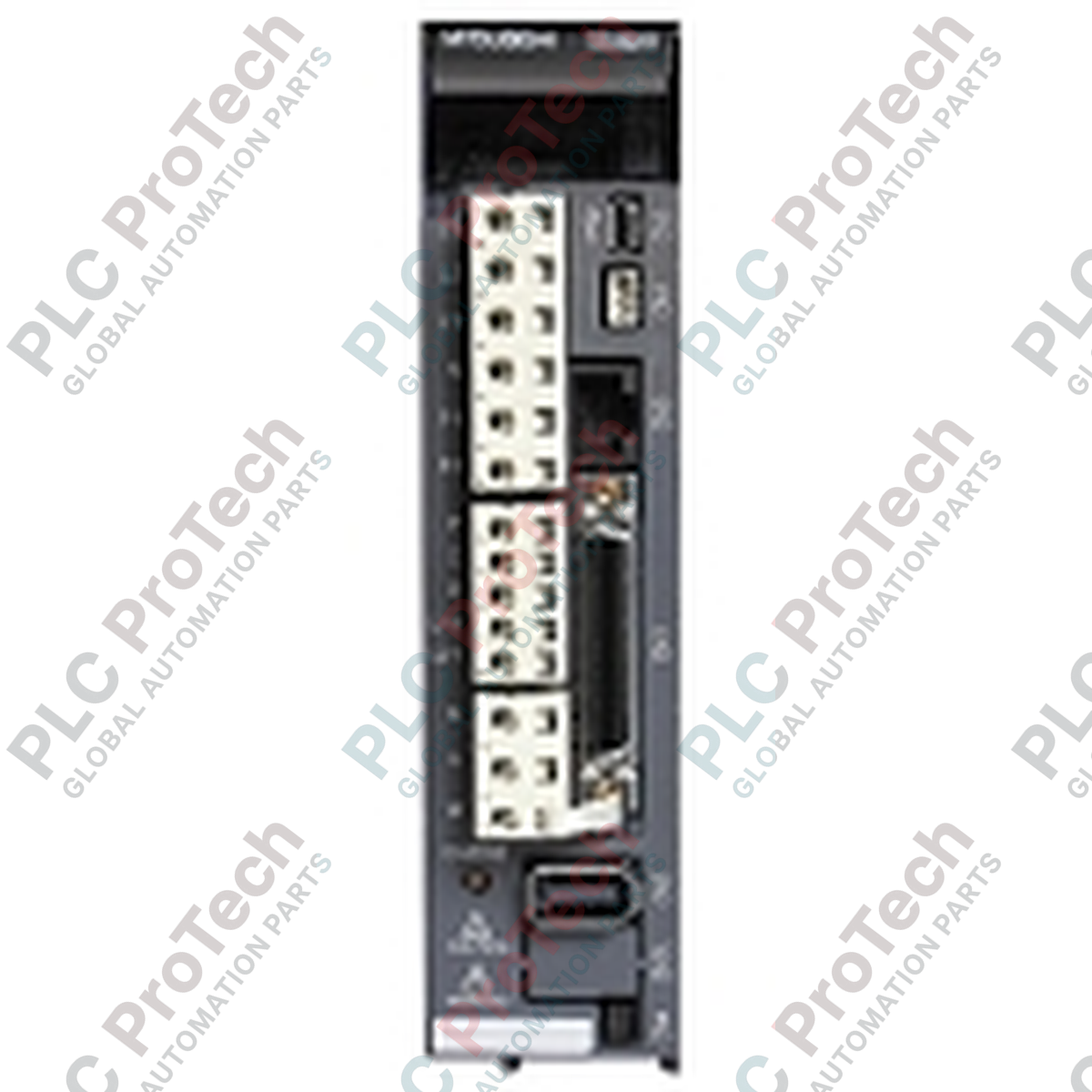
Connections and Interfaces
| Connector / Terminal |
Function / Circuit Assignment |
| CN1A / CN1B |
SSCNET III network connection ports (Optical fiber duplex connectors) |
| CN2 |
Encoder feedback connection for the HF or HC series servo motor |
| CN3 |
Digital input/output signal interface (interlock, emergency stop, limit switches) |
| CN5 |
USB communication port for PC tool setup and online diagnostics |
| L1, L2, L3 |
Main power circuit input terminal block |
| L11, L21 |
Control power circuit input terminal block |
| U, V, W |
3-phase power output connection to servo motor windings |
Empirical Engineering Insights
Alternative Models & Compatibility
When migrating a system from the MR-J2S-60B series, note that the SSCNET III optical fiber connector format differs physically from the original SSCNET configuration. The MR-J3-60B requires specialized high-speed optical fiber cables (such as MR-J3BUS) which utilize standard locking tabs. Intermixing old and new optical connection configurations is not possible without an optical media converter or controller-level interface card replacement.
Application Pitfalls & Engineering Notes
To avoid high thermal loading in enclosed electrical cabinets, design layout spacing strictly: maintain at least 10 mm clearance on either side of the chassis, and 40 mm clearance above and below. If routing SSCNET III fiber optic cables, enforce a minimum bending radius of 25 mm. Exceeding this limit will result in optical signal attenuation, manifesting as communication timeouts or non-specific "AL.37 Parameter Error" fault triggers.
Commissioning & Wiring Tips
If configuring the absolute position detection system, always insert an active MR-BAT or MR-J3BAT battery pack before starting the system calibration. Loss of control voltage without an active battery backup instantly clears the stored encoder home coordinates, requiring manual re-homing procedures upon subsequent control system re-initialization.
Installation Guidelines
CRITICAL WARNING: Verify all AC input power feeds are completely isolated, disconnected, and locked out prior to handling any terminals. Wait a minimum of 15 minutes after power-down to allow internal high-voltage capacitors to bleed energy safely. Check that the internal red charge LED is completely extinguished before initiating any dynamic resistance or terminal verification tests.
1
Mount the servo amplifier vertically to a rigid, metallic panel surface. Secure the chassis via the mounting holes to ensure optimal heat dissipation and ground contact.
2
Wire the control circuit supply voltage terminals (L11, L21) and main input terminals (L1, L2, L3) using appropriate gauge wire, adhering to correct regional fuse/breaker guidelines.
3
Connect the motor output lines (U, V, W) to the corresponding terminals on the motor. Pay absolute attention to match phases precisely—reversing phase wiring here will trigger a run-away feedback condition and cause damage.
4
Insert the fiber optic cables securely into the CN1A and CN1B ports. Listen for an audible click confirming the mechanical locks have engaged correctly.