Description
Operating on a 200V class supply, the Mitsubishi Electric MR-J4-10A single-axis servo drive is engineered to deliver highly responsive closed-loop motion control for 0.1 kW rotary, linear, and direct-drive motors within the MELSERVO-J4 automation platform. This unit interfaces seamlessly via a general-purpose command interface, accommodating both high-speed pulse train train positioning and analog speed or torque control methods. Equipped with 22-bit high-resolution encoder feedback, it achieves remarkable micro-positioning precision. Its robust diagnostic suite and integrated Safe Torque Off (STO) safety mechanisms ensure high reliability and compliance in demanding industrial system designs.
Key Features
-
22-Bit High-Resolution Feedback: Interfaces directly with high-resolution encoders (4,194,304 pulses/rev) for exceptionally smooth rotation and precise positioning.
-
Flexible Input Configuration: Universally supports single-phase or three-phase 200V AC to 240V AC power supply lines.
-
General-Purpose Interface: Accommodates pulse train commands up to 4 Mpulses/s (differential receiver) alongside ±10V analog speed and torque commands.
-
Advanced Vibration Suppression: Employs adaptive tuning, machine end vibration control, and robust filters to suppress mechanical resonance automatically.
-
Integrated Safety Function: Features built-in Safe Torque Off (STO) certified to EN ISO 13849-1 Category 3 PL e and IEC 61508 SIL 3.
Applications
- Semiconductor and liquid crystal assembly machinery.
- High-speed pick-and-place electronic component insertion.
- Precision packaging, labeling, and bottle-capping machines.
- Cartesian coordinate robots and small-scale CNC machining axes.
Technical Specifications
| Specification Parameter |
Value / Rating |
| Manufacturer |
Mitsubishi Electric |
| Model / SKU |
MR-J4-10A |
| Series |
MELSERVO-J4 |
| Output Rated Power |
0.1 kW (100 W) |
| Output Voltage / Current |
Three-phase 170 V AC / 1.1 A |
| Main Circuit Supply Input |
Single-phase or Three-phase 200 V AC to 240 V AC, 50/60 Hz |
| Allowable Input Voltage Fluctuation |
170 V AC to 264 V AC |
| Control Circuit Supply Input |
Single-phase 200 V AC to 240 V AC, 50/60 Hz (0.2 A to 0.3 A) |
| Control System |
Sinusoidal wave PWM control and current control system |
| Command Interface |
General-purpose interface (Pulse Train, Analog, RS-422/RS-485, USB) |
| Safety Standard Compliance |
EN ISO 13849-1 Category 3 PL e, IEC 61508 SIL 3, EN 62061 SIL CL 3 |
| Environmental Protection Rating |
IP20 (Self-cooling / Open design) |
| Ambient Operating Temperature |
0 to 55 degC (no freezing) |
| Net Weight |
0.8 kg |
| Shipping Weight (Calculated) |
2.0 kg |
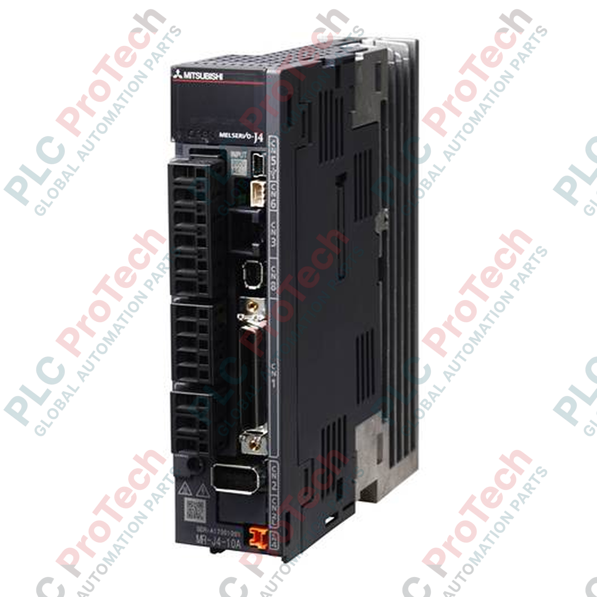
Connections and Interfaces
| Port / Connector |
Function / Circuit Assignment |
| L1, L2, L3 |
Main circuit power input (3-Phase AC 200V-240V). Connect to L1 and L2 for Single-Phase. |
| L11, L21 |
Control circuit power supply input (Single-Phase AC 200V-240V). |
| U, V, W |
Servo motor output terminals. |
| CN1 |
Analog / pulse train command inputs and digital I/O signals. |
| CN2 |
Encoder feedback interface connection. |
| CN3 |
RS-422 / RS-485 serial communication port. |
| CN5 |
USB port for MR Configurator2 configuration software. |
| CN8 |
Safe Torque Off (STO) input signal interface. |
Alternative Models & Compatibility
The MR-J4-10A features the standard general-purpose analog/pulse interface. It is a direct functional upgrade for legacy MR-J3-10A drives. However, configuration file parameter transfer must be performed via MR Configurator2 to map parameters accurately. Note that the MR-J4-10A is functionally and physically distinct from the MR-J4-10B, which operates exclusively on the high-speed fiber-optic SSCNET III/H network; they cannot be substituted for one another without swapping out the control network hardware.
Application Pitfalls & Engineering Notes
When configuring the MR-J4-10A for single-phase operation, ensure that the power supply wiring is connected to the L1 and L2 terminals. If single-phase power is applied without adjusting the parameter settings to disable three-phase open phase monitoring, the amplifier will trigger an AL 10 (undervoltage) or AL 12 (memory error/phase open) alarm. Proper heat-dissipation clearance must be maintained when mounting adjacent to other units inside dense panels; a minimum distance of 10 mm on either side is recommended for optimal convection cooling.
Commissioning & Wiring Tips
To protect the high-resolution 22-bit absolute feedback signal from electromagnetic interference, always utilize double-shielded, twisted-pair cable for the CN2 encoder interface. Ensure the amplifier's ground terminal is bonded back to the primary electrical panel ground plate via a low-impedance connection. If feedback-line signal errors occur (such as AL 1A or AL 50), verify that the shielding connection at the motor-end connector has not been bypassed, and consider installing a high-performance power line filter on the main AC incoming power line.
Installation Guidelines
CRITICAL WARNING
Risk of electric shock and residual energy hazard. Disconnect all main line power before installing, wiring, or servicing this equipment. Wait a minimum of 15 minutes after power-down to allow internal high-voltage capacitors to fully discharge before handling terminals.
-
1
Mount the servo amplifier vertically on a flat, vibration-free surface inside a metallic, IP54-rated control cabinet to safeguard against dust and oil mist.
-
2
Wire the incoming 200V power lines to L1, L2, L3 (and L11, L21 control power) using specified wire gauges and short-circuit protection fuses.
-
3
Connect the U, V, and W motor terminal leads matching phase orientation directly to the servo motor power plug. Never apply commercial power directly to U, V, or W.
-
4
Attach control inputs to CN1, plug the motor encoder cable into CN2, and insert the STO bypass plug into CN8 if safe torque functions are not used.