Description
Executing high-speed industrial sequence logic within the MELSEC Q Series platform, the Mitsubishi Electric Q03UDCPU is designed as a high-performance Universal PLC CPU module. It features an advanced processing engine capable of executing basic sequence instructions down to 20 nanoseconds, rendering it ideal for high-speed packaging, multi-axis coordination, and distributed plant control architectures. Program storage is secured by a 30K-step program capacity (120 KB), with extensive expandable file registers to accommodate complex automation recipes and extensive system parameter configuration.
Features
- High-speed instruction execution of 20 ns for LD X0 and 40 ns for MOV D0 D1.
- Flexible program capacity of 30K steps (120 KB) supporting multi-program system designs.
- Multi-language support including Relay Symbol Word, Structured Text (ST), Function Block (FB), and MELSAP 3 (SFC).
- Dual direct-access I/O system mapping (refresh mode or direct I/O execution via DX/DY addressing).
- Robust internal memory system containing 192 KB standard RAM and 1024 KB standard ROM.
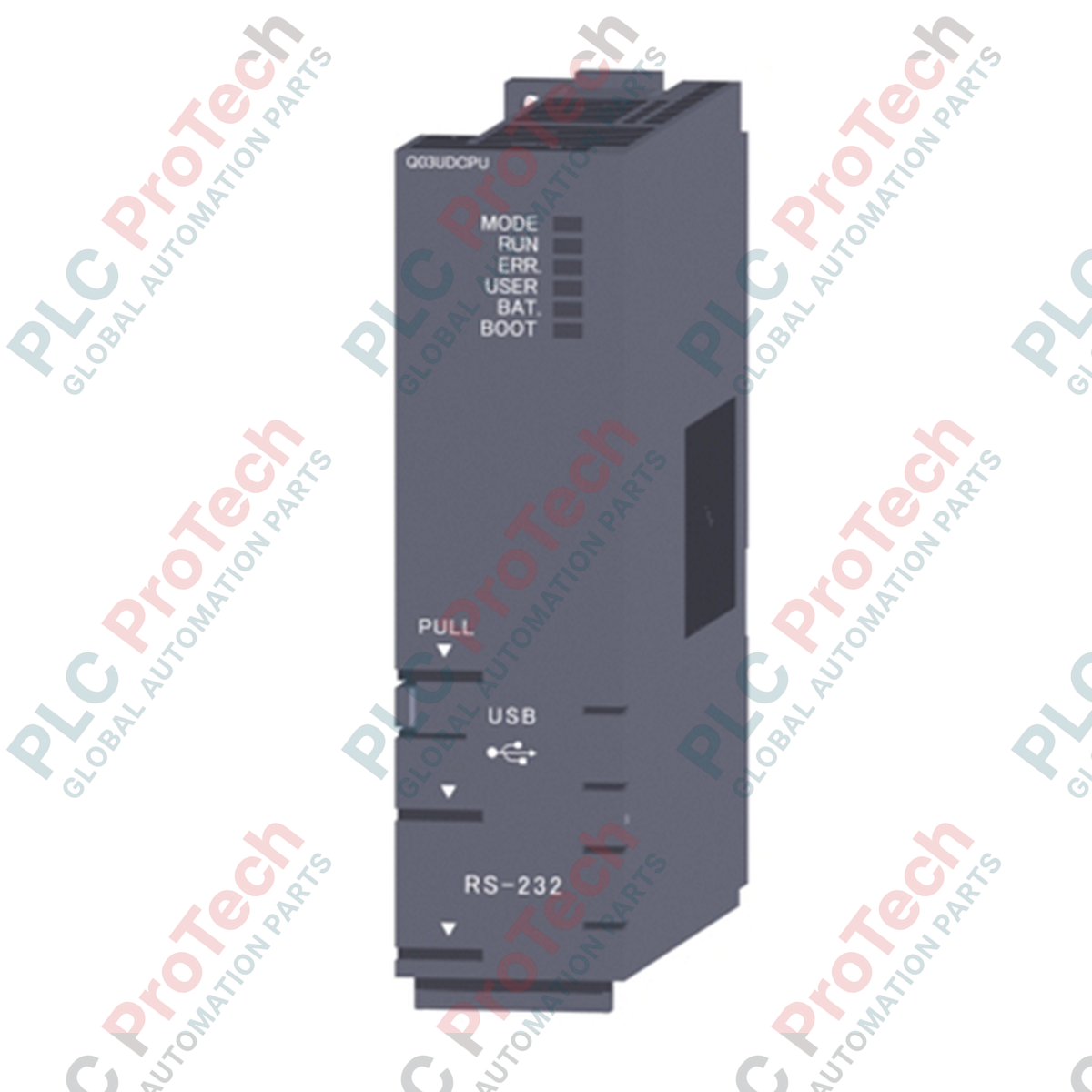
- Dual interface architecture featuring on-board USB (Mini-B) and RS-232 connection interfaces for seamless local diagnostics.
Applications
-
High-Speed Packaging Systems: Real-time indexing, bagging, and synchronization of auxiliary motion axes.
-
Automotive Assembly Lines: Coordinated conveyor sequencing, multi-CPU architecture integration, and distributed device level networking.
-
Process Plant Subsystems: Water treatment, cleanroom management, and environmental monitoring control platforms.
Technical Specifications Table
| Parameter |
Specification Value |
| Manufacturer |
Mitsubishi Electric |
| Model Number |
Q03UDCPU |
| Control Method |
Stored program cyclic/iteration operation |
| Instruction Execution Speed |
20 ns (LD X0), 40 ns (MOV D0 D1) |
| Program Capacity |
30K steps (120 KB) |
| Standard RAM |
192 KB |
| Standard ROM |
1024 KB |
| Max. Number of I/O Points |
4096 points (X/Y0 to FFF) |
| Internal Current Consumption (DC 5V) |
0.33 A |
| Operating Ambient Temperature |
0 to 55 degC |
| Storage Ambient Temperature |
-25 to 75 degC |
| Ambient Operating Humidity |
5 to 95% RH, non-condensing |
| Dimensions (H x W x D) |
98 mm x 27.4 mm x 89.3 mm |
| Net Weight |
0.20 kg |
| Shipping Weight (Calculated) |
2.0 kg |
| Country of Origin |
Japan |
Connections and Interfaces
| Port / Physical Interface |
Function and Assignment |
| USB (Mini-B) Port |
High-speed GX Works2 / GX Developer programming, monitoring, and debugging link. |
| RS-232 Connector |
Serial communications link for HMI interfaces, modems, and programming peripherals. |
| Memory Card Slot |
Supports SRAM cards (up to 8 MB), Flash cards (up to 4 MB), or ATA cards (up to 32 MB). |
Alternative Models & Compatibility
The Q03UDCPU provides a direct upgrade pathway from legacy Q03UD units. Unlike the Q03UDECPU, this model does not feature a built-in Ethernet (RJ45) port. If industrial Ethernet connectivity (EtherNet/IP or Modbus TCP) is required, you must integrate an external communication card, such as the QJ71E71-100 module, or utilize a Q03UDECPU or Q03UDVCPU module instead.
Application Pitfalls & Engineering Notes
When deploying the Q03UDCPU in multi-CPU configurations alongside motion or robot CPUs, pay close attention to the parameter settings for the high-speed inter-CPU communication shared memory. Over-allocating data in the shared memory registers without matching cycle updates in the system parameters can lead to immediate multi-CPU synchronization faults (WDT errors or Error 1400).
Commissioning & Wiring Tips
Verify the physical toggle position of the RUN/STOP/RESET switch prior to download operations. If storing active runtime values or recipes in standard RAM, ensure that the system lithium battery (Q6BAT) is functional. If the red BAT LED illuminates, immediately backup your registers to avoid data loss upon subsequent 24V DC backplane power cycles.
Installation Guidelines
CRITICAL WARNING: Never install or extract the PLC CPU module from the main backplane while the rack power supply module (e.g., Q61P) is energized. Doing so will cause severe physical damage to the module backplane connectors and internal logic chips.
1
De-energize the main line voltage feeding the power supply module and verify using a voltmeter that no residual voltage remains.
2
Align the lower hook of the CPU module into the mounting guide hole on the base unit slot.
3
Push the top of the module firmly onto the base plate until the module lock latch clicks securely into place. Secure the module further using a M3 holding screw if high vibration levels are anticipated.