Description
Optimizing high-speed sequence control and multi-discipline automation architectures, the Mitsubishi Electric Q26UDVCPU serves as a high-performance central processing unit within the modular MELSEC Q Series platform. This controller is engineered to process massive instruction volumes with exceptionally low instruction execution times, making it ideal for highly synchronized multi-CPU systems, complex motion paths, and large-scale manufacturing cells. With integrated communication interfaces and an ultra-fast backplane transfer rate, this controller minimizes network latency and cycle times while maintaining deterministic control over local and distributed physical I/O.
Key Features
- High-speed sequence execution capability with an LD instruction speed of 1.9 nanoseconds.
- Generous user program capacity of 260K steps to support complex control logic and extensive structured programming.
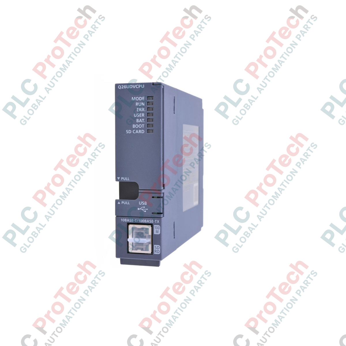
- Built-in 100BASE-TX/10BASE-T Ethernet port for seamless integration into plant-wide networks and direct database connectivity.
- Integrated high-speed USB (Mini-B) port for local programming, diagnostics, and monitoring via GX Works2 or GX Works3.
- Dedicated SD memory card slot for localized data logging, recipe storage, and firmware or program backups.
- Support for multi-CPU configurations, allowing load distribution between sequence, motion, and process control modules.
Applications
- High-speed packaging, sorting, and material handling systems requiring rapid product registration and response times.
- Semiconductor fabrication equipment and precision electronic component assembly lines.
- Automotive assembly cells and robotic coordination systems utilizing synchronized multi-CPU backplanes.
- Large-scale water treatment facilities, food and beverage processing, and continuous batching systems.
Technical Specifications
| Parameter |
Specification |
| Manufacturer |
Mitsubishi Electric |
| Model Number |
Q26UDVCPU |
| Series |
MELSEC Q Series (Universal Model) |
| Control Method |
Stored program cyclic operation |
| Program Capacity |
260K Steps (1040K Bytes) |
| LD Instruction Execution Speed |
1.9 ns |
| I/O Points |
4096 Points (8192 Points when using remote I/O) |
| Programming Languages |
Relay Symbol (Ladder), Instruction List, SFC (MELSAP3/MELSAP-L), Function Block, Structured Text (ST) |
| Onboard Interfaces |
Ethernet (RJ45), USB (Mini-B), SD Card Slot |
| Internal Current Consumption |
0.58 A (at 5 VDC) |
| Country of Origin |
Japan |
| Shipping Weight (Calculated) |
0.45 kg (Module only: 0.22 kg) |
| Package Dimensions (Calculated) |
15.0 cm x 13.0 cm x 5.5 cm |
Alternative Models & Compatibility
The Q26UDVCPU serves as a high-speed upgrade path for legacy Q25HCPU and Q26UDHCPU systems. When migrating legacy code to the "V" series CPU, verify that all motion or specialized function module drivers are updated, and check your GX Works2/GX Works3 software environment for compiled parameter compatibility. This CPU utilizes a standard Q-series base unit but provides faster bus speeds for compatible High-Speed Universal modules.
Application Pitfalls & Engineering Notes
When utilizing the integrated SD card slot for continuous data logging or recipe handling, only industrial-grade SD/SDHC cards formatted in FAT16 or FAT32 should be used. Using commercial-grade cards in high-temperature or high-vibration control cabinets can lead to memory sector failure, resulting in system blockages or application diagnostics faults (e.g., "FILE ACCESS ERROR"). Maintain panel ambient temperatures below 55 degC to prevent thermal throttling during high-speed multi-axis execution cycles.
Commissioning & Wiring Tips
To protect the Ethernet physical layer from industrial electromagnetic interference (EMI), always deploy category 5e or higher double-shielded twisted pair (S/FTP) cabling. Keep communication lines separated by at least 10 cm from high-voltage motor lines or variable frequency drive (VFD) output cables. Ensure that the base unit's functional ground terminal is connected to an independent low-impedance ground point to prevent common-mode noise issues on the backplane data lines.
Installation Guidelines
CRITICAL WARNING: ELECTRICAL SHOCK AND SYSTEM DAMAGE
Isolate and lock out all external power sources feeding the main base unit and any associated I/O racks before inserting, removing, or wiring the controller. Failure to fully de-energize the rack before card insertion may cause arc flash, permanent damage to the CPU backplane interface, or unpredictable control state initialization.
1
Align the upper hook of the Q26UDVCPU module with the corresponding guide slot located on the Q Series base unit.
2
Push the bottom portion of the CPU firmly into the base unit's multi-pin connector until the lock mechanism clicks securely.
3
Secure the module to the base plate using the integrated module fixing screw (tightening torque: 0.36 to 0.48 N-m) to prevent vibration displacement.
4
Connect the Ethernet and programming cables, verifying that the connector latching mechanisms engage cleanly. Apply power to the power supply module and verify that the "MODE" LED lights up green.