Description
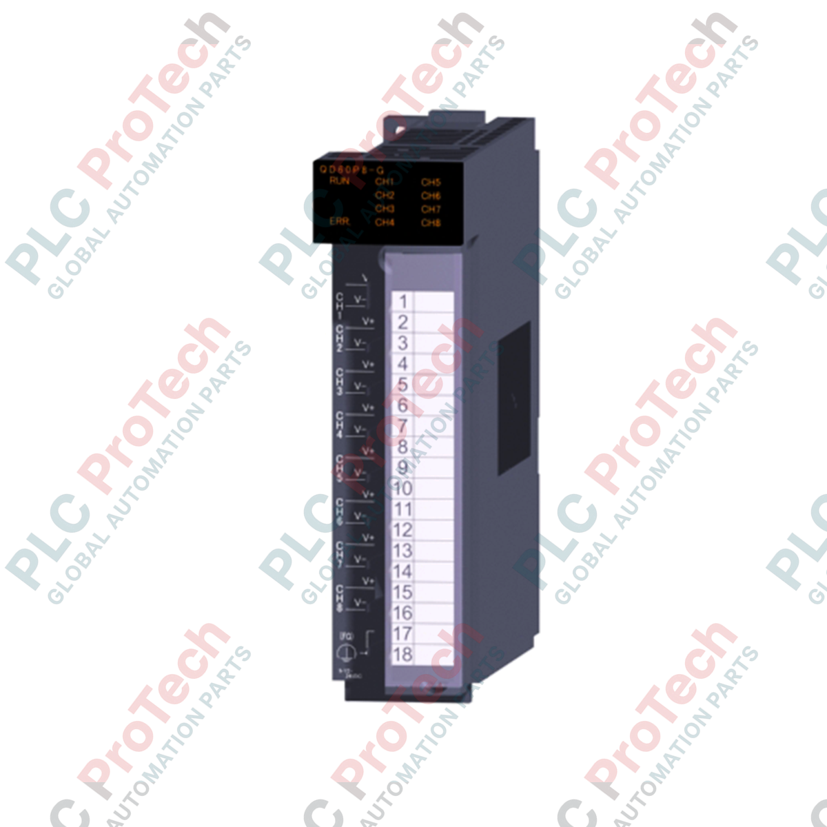
Optimized for high-density pulse logging in multi-source electrical environments, the Mitsubishi Electric QD60P8-G serves as a high-performance 8-channel pulse input interface for the MELSEC Q control platform. By featuring complete inter-channel galvanic isolation, this module mitigates ground potential differences and signal interference when monitoring disparate field instruments. The unit processes single-phase pulse inputs across flexible voltage ranges, making it an ideal choice for complex utility tracking, flow metering, and synchronization tasks within industrial automation infrastructures.
Features
-
8 Isolated Channels: Independent electrical isolation between all input channels protects the backplane and adjacent modules from common-mode noise and ground loops.
-
Configurable Counting Speeds: Selectable input filters ranging from 0.1 pps up to 30 kpps allow matching with low-frequency mechanical contacts or high-frequency solid-state encoders.
-
Flexible Signal Levels: Supports both 5VDC and 12 to 24VDC signal levels for direct interfacing with various sensor types.
-
Versatile Counter Modes: Operates in both linear counter and ring counter modes with support for 16-bit binary sampling and 32-bit integrated count values.
-
Robust Isolation Rating: Withstands up to AC 1780 V for 1 minute between channels, ensuring survivability in harsh electrical environments.
Applications
- Utility and energy monitoring (integrating pulse outputs from gas, water, and electricity meters).
- Flow rate calculation and fluid dosing control systems.
- Conveyor tracking and material throughput logging.
- High-density piece counting and production rate monitoring.
Technical Specifications
| Parameter |
Value / Specification |
| Manufacturer |
Mitsubishi Electric |
| Model Code |
QD60P8-G |
| Product Series |
MELSEC Q Series |
| Module Type |
Inter-channel Isolated Pulse Input Unit |
| Number of Channels |
8 channels (individually isolated) |
| Count Input Signal Phase |
1-phase input |
| Signal Voltage Levels |
5VDC / 12 to 24VDC |
| Maximum Counting Speed |
30 kpps (selectable: 30 kpps, 10 kpps, 1 kpps, 100 pps, 50 pps, 10 pps, 1 pps, 0.1 pps) |
| Count Ranges |
Sampling: 16-bit binary (0 to 32767)
Integrated count: 32-bit binary (0 to 99999999)
Input pulse value: 32-bit binary (0 to 2147483647) |
| Counter Modes |
Linear counter, Ring counter |
| Withstand Voltage |
Between channels: AC 1780 V for 1 min
Between AC terminals and ground: AC 1500 V for 1 min
Between DC terminals and ground: AC 500 V for 1 min |
| Insulation Resistance |
DC 500 V, 5 MOhm or more |
| Wiring Interface |
18-point screw terminal block (M3 screws) |
| I/O Points Occupied |
32 points (intelligent function module classification) |
| Internal Current Consumption |
0.58 A (at 5VDC) |
| Dimensions (H x W x D) |
98 mm x 27.4 mm x 90 mm |
| Net Weight |
0.17 kg |
| Shipping Weight (Calculated) |
1.10 kg |
Empirical Engineering Insights
Alternative Models & Compatibility
The QD60P8-G fits directly into any standard Q-series backplane. For legacy migrations, ensure that your existing engineering configuration tool (GX Works2 or GX Works3) has the corresponding QD60P8-G parameter profiles installed. If upgrading from non-isolated pulse input modules, review your grounding layouts as the isolated design of this model removes the necessity of external loop isolation barriers.
Application Pitfalls & Engineering Notes
When configuring the input pulse counting speed, select the filter threshold closely matching your physical signal frequency. Setting the filter rate excessively high (e.g., 30 kpps for a 10 pps flow meter) can cause mechanical contact bounce or electrical transient noise to register as extra, spurious counts. Ensure that the logic level voltage corresponds to the specific physical wiring points to prevent thermal overload on the input channels.
Commissioning & Wiring Tips
Always route the pulse input cables separately from high-voltage AC motor lines to prevent electromagnetic coupling. To secure high-noise immunity, utilize shielded twisted-pair (STP) cabling, grounding the shield at a single point on the control panel chassis. Do not over-torque the M3 terminal screws beyond the recommended limits (typically 0.42 to 0.58 N-m) to prevent strip damage to the internal connector block.
Installation Guidelines
CRITICAL WARNING
Isolate and lock out all primary and auxiliary power sources before installing, removing, or wiring the module. Failure to de-energize the PLC backplane and field wiring prior to module insertion can result in permanent processor damage, module destruction, or electrical shock hazard.
1
Mount the QD60P8-G onto the Q-series base unit by inserting the module's bottom retaining tab into the base slot, and then pivot the module firmly into place until it seats securely.
2
Secure the module to the base unit using the top mounting screw. This maintains connection integrity under high-vibration conditions.
3
Wire your pulse sources to the 18-point terminal block matching your signal level configurations (5VDC or 12 to 24VDC pins).
4
Apply backplane and field power, then proceed with digital filtering configuration and counter mode calibration within your GX Works programming software environment.