Description
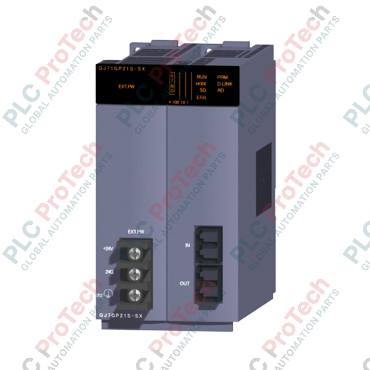
To establish deterministic, high-speed backbone communications within a MELSEC Q Series control architecture, the Mitsubishi Electric QJ71GP21S-SX CC-Link IE Controller Network Unit serves as a high-performance fiber-optic interface. Operating on a gigabit transmission line, this module coordinates high-volume data exchanges using a token ring method across a dual-loop path topology. Designed with a dedicated external power supply terminal, the QJ71GP21S-SX ensures network loop integrity is fully maintained even if individual PLC base units are de-energized, preventing ring segmentation in critical manufacturing plants.
Features
-
1 Gbps Transmission Speed: Utilizes high-bandwidth gigabit Ethernet physical layers to execute high-speed, cyclic transmissions across the industrial network.
-
Redundant Dual-Loop Path: Employs a double-loop optical fiber configuration that executes auto-loopback routing instantly upon cable damage or station power failures.
-
External Power Supply Support: Accepts DC 24V auxiliary power to keep communication circuits operational independently of the host PLC backplane status.
-
Extended Station Configuration: Connects up to 120 normal stations when coupled with Universal QCPU management units, extending control across plant environments.
-
Large Link Capacity: Accommodates up to 32K points for link relays (LB) and 128K points for link registers (LW) in extended transmission mode.
Applications
-
Automotive Assembly Plants: High-speed synchronization of multi-axis assembly bays and welding robots across wide shop floors.
-
Water and Wastewater Treatment: Long-distance network loops connecting isolated pumping substations up to 550 meters apart without repeater stations.
-
Paper & Pulp Manufacturing: High-throughput, noise-immune optical communication lines routing real-time process control data through high-interference processing zones.
Technical Specifications
| Parameter |
Specification Value |
| Manufacturer |
Mitsubishi Electric |
| Model Reference |
QJ71GP21S-SX |
| Network Type |
CC-Link IE Controller Network |
| Communication Speed |
1 Gbps |
| Transmission Path Format |
Double loop (Token ring method) |
| Maximum Stations |
120 stations (with Universal QCPU management station) |
| Optical Fiber Spec |
Graded-index (GI) multi-mode optical fiber (1000BASE-SX) |
| Connector Interface |
Duplex LC type connector |
| Laser Safety Class |
Class 1 (JIS C 6802, IEC 60825-1) |
| Maximum Loop Length |
66,000 meters (with 120 units connected) |
| Inter-Station Distance |
Max. 550 meters |
| External Power Input |
DC 20.4 V to 31.2 V (Current consumption: 0.28 A) |
| Internal DC 5V Consumption |
0.90 A |
| Occupied I/O Points |
48 points (2 slots required: 16 empty points + 32 intelligent points) |
| Device Dimensions |
98 mm (H) x 55.2 mm (W) x 90 mm (D) |
| Net Weight |
0.28 kg |
| Shipping Weight (Calculated) |
1.30 kg |
Connections and Interfaces
| Connector / Terminal |
Physical Form |
Functional Assignment |
| PORT 1 |
Duplex LC Optical Interface |
Primary network transmit/receive fiber-optic connection (Channel 1) |
| PORT 2 |
Duplex LC Optical Interface |
Secondary network transmit/receive fiber-optic connection (Channel 2) |
| 24VDC Terminal Block |
Screw-clamp connection |
External power input (DC 20.4V to 31.2V) to power loop transceiver during PLC down-time |
Empirical Engineering Insights
Alternative Models & Compatibility
The "S" suffix identifies this model as having external power supply capabilities. While it maintains backward code compatibility with the standard QJ71GP21-SX unit in GX Works2 or GX Developer programming environments, replacing a standard unit with the QJ71GP21S-SX requires external DC 24V field wiring to leverage its loop backup protection function. Always verify your current configuration utility parameters when shifting between high-performance and universal QCPU backplanes, as maximum node counts scale from 64 to 120.
Application Pitfalls & Engineering Notes
Multi-mode GI fibers must conform strictly to 1000BASE-SX specifications. Inserting standard telecom single-mode fibers will cause immediate transmitter saturation or high optical attenuation faults. Ensure the bend radius of the optical fiber runs inside enclosures does not drop below the manufacturer's specified limit to avoid micro-bending losses, which directly generate network-level link-loss anomalies and token drops.
Commissioning & Wiring Tips
Before powering up the system, use a calibrated optical power meter to confirm fiber run losses are well within the 1000BASE-SX link budget. Ensure that Port 1 Out is cross-patched to Port 2 In on downstream nodes as per standard dual-loop layouts. When configuring redundant tracks, the external auxiliary DC supply must be powered through a dedicated class 2 power source with clean grounding to prevent industrial noise and transient surges from interfering with the gigabit transceivers.
Installation Guidelines
CRITICAL WARNING: Disconnect all primary rack power and the DC 24V auxiliary external power source prior to physical installation or module extraction. Failure to fully de-energize circuits may lead to transient arc discharges, hardware failure of the internal bus transceivers, or erratic signals on adjacent MELSEC Q modules.
-
1
Align the bottom-fixing lug of the QJ71GP21S-SX module with the corresponding slot on the MELSEC Q base unit.
-
2
Securely push the top part of the module into the backplane connector until it clicks, and tighten the top mounting screw to the specified torque.
-
3
Connect the external DC 24V auxiliary power lines to the dedicated auxiliary input terminal block, ensuring correct polarity.
-
4
Remove protective dust caps and insert the Duplex LC multi-mode optical fiber connectors into Port 1 and Port 2.