Description
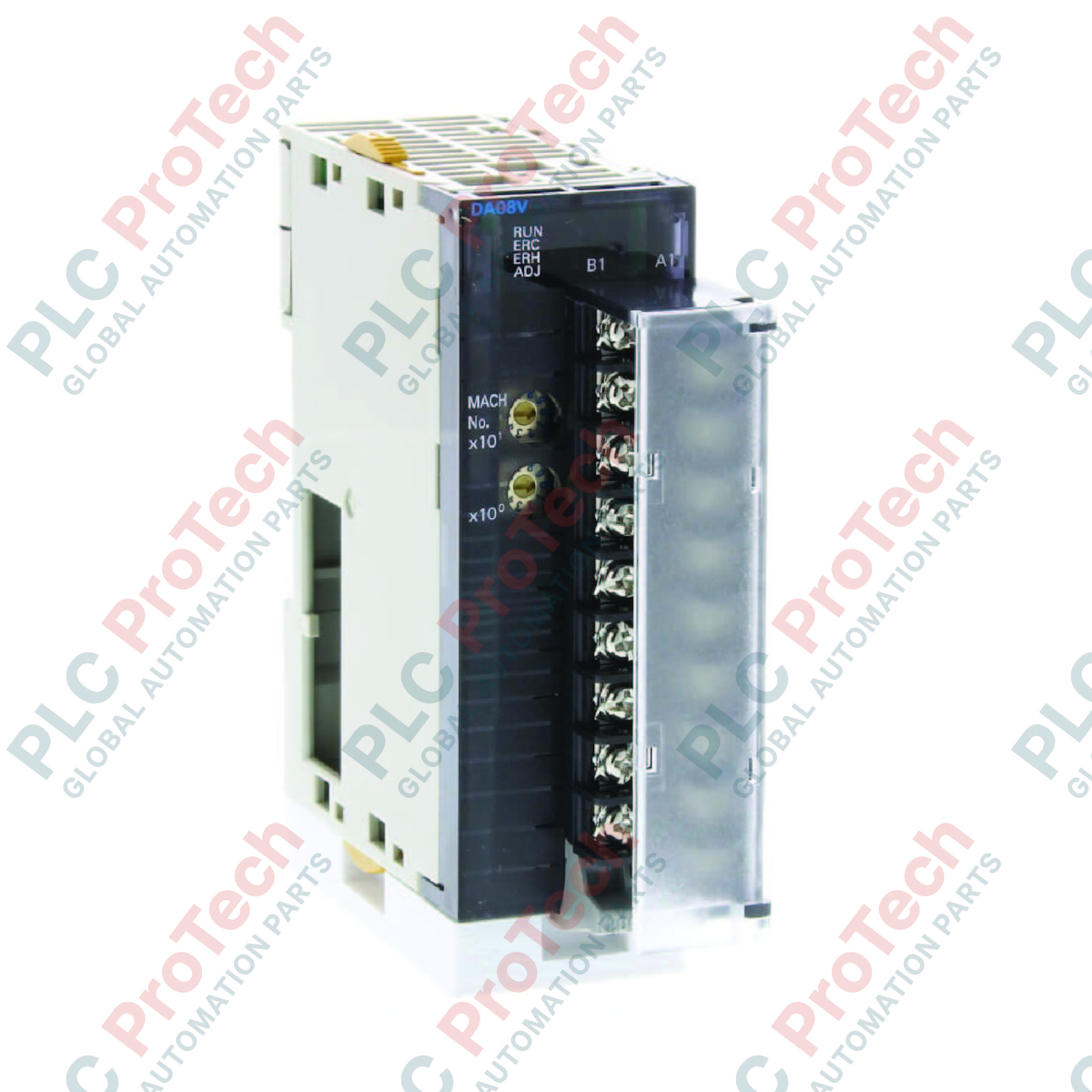
Configured for high-density voltage command applications, the Omron CJ1W-DA08V delivers eight independent analog output channels within a single-slot CJ-series form factor. This module serves as a critical interface between Omron CJ1G, CJ1H, or CJ2M CPU controllers and external field hardware such as variable frequency drives (VFDs), control valves, and actuators. Built-in configuration parameters permit localized range adjustments and scaling directly in the PLC memory map, optimizing loop performance and eliminating the need for external signal conditioners.
Key Features
-
Eight Independent Outputs: Provides high-density voltage command capabilities within a single PLC rack slot.
-
Selectable Signal Ranges: Individual configuration for each channel supporting 1 to 5 V, 0 to 5 V, 0 to 10 V, and -10 to 10 V.
-
Flexible Performance Modes: Configurable resolution settings of 1/4000 (standard mode) or 1/8000 (high-resolution mode).
-
Synchronized Conversion Rates: Achieves a 1 ms per point conversion speed in standard mode, and up to 250 us per point in high-speed mode.
-
Removable Terminal Block: Simplifies initial cabinet pre-wiring and facilitates rapid hot-swapping during maintenance cycles.
Target Applications
-
VFD Speed Control: Direct speed referencing for variable frequency drives via standard 0-10 V or 1-5 V analog inputs.
-
Proportional Valve Positioning: Dynamic control of hydraulic and pneumatic proportional valves in positioning loops.
-
HVAC Damper Actuation: Multi-channel modulation of air volume dampers and thermal control elements.
-
Test Bench Signal Simulation: Generating precise voltage references for automated test systems.
Technical Specifications
| Parameter |
Value / Specification |
| Manufacturer |
Omron Industrial Automation |
| Model Number |
CJ1W-DA08V |
| Output Channels |
8 Voltage Outputs |
| Output Voltage Ranges |
1 to 5 V, 0 to 5 V, 0 to 10 V, -10 to 10 V |
| Resolution Modes |
1/4000 (Standard), 1/8000 (High-Resolution) |
| Conversion Speed |
1 ms/point (at 1/4000), 250 us/point (at 1/8000) |
| Accuracy at 25 degC |
+/-0.3% of Full Scale |
| Internal Current Consumption |
140 mA at 5 VDC |
| External Power Requirement |
24 VDC (+10% / -15%), 140 mA maximum |
| Connection Type |
M3 Removable Terminal Block |
| Unit Allocation |
1 Special I/O Unit Number |
| Country of Origin |
Japan |
| Shipping Weight (Calculated) |
0.35 kg |
| Package Dimensions (Calculated) |
110 mm x 90 mm x 31 mm |
Empirical Engineering Insights
Alternative Models & Compatibility
The CJ1W-DA08V is designed strictly for voltage output architectures. If your application demands loop-powered current outputs (e.g., 4-20 mA), you must utilize the CJ1W-DA08C companion module. Both modules occupy a single-slot footprint on CJ1 and CJ2 backplanes and use similar data memory allocations, simplifying engineering conversions during retrofits.
Application Pitfalls & Engineering Notes
Note that resolution and conversion speeds are system-locked. Setting the conversion resolution to 1/4000 restricts the conversion speed to 1 ms per point. Attempting to force a 250 us speed configuration within PLC memory while maintaining a 1/4000 resolution limit will generate an I/O configuration error. Additionally, ensure the external 24 VDC power supply is turned on before or simultaneously with the PLC CPU; failing to do so may register an output error flag on startup.
Commissioning & Wiring Tips
To mitigate electrostatic and electromagnetic interference in high-precision loops, always use twisted-pair shielded control cables. Terminate the shield exclusively to the functional ground (FG) terminal on the PLC panel side, leaving the field-device end floating. This prevents harmful ground loops from creating artificial offsets in your 0-10 V signals.
Installation Guidelines
CRITICAL WARNING:
De-energize the entire PLC system and any connected field instruments before sliding the CJ1W-DA08V module onto the DIN rail or attaching/removing the terminal block. Hot-plugging this unit or its external power terminals can result in permanent damage to internal bus transceivers or erratic control signals to downstream actuators.
1
Backplane Mounting: Align the module hooks with the lock holes on the adjacent CJ-series unit and slide the module firmly in place. Pivot the blue locking sliders at the top and bottom forward until they click.
2
External Power Wiring: Connect a clean 24 VDC source to the dedicated power terminals on the removable block. Ensure the power routing is fused and isolated from high-power inductive switching circuits.
3
Signal Connection: Torque the field signal wires to the M3 terminals, keeping analog wiring physically separated from high-voltage AC cables inside the wire trunking.