Description
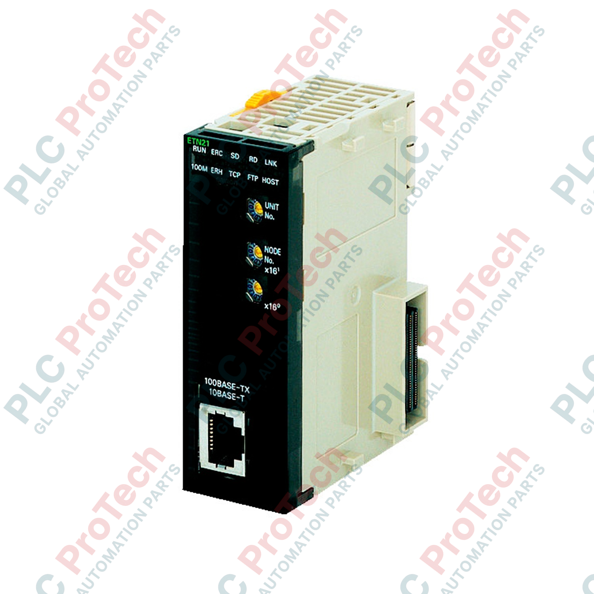
Facilitating seamless network integration, the Omron CJ1W-ETN21 Ethernet communications module links CJ-series controllers to higher-level enterprise systems and peer control networks. This CPU Bus Unit mounts directly onto a CJ-series CPU Rack or Expansion Rack, providing dedicated 100Base-TX and 10Base-T physical interface ports. Engineered for stable industrial data exchange, the module supports standard TCP/IP and UDP/IP protocols, allowing multiple simultaneous socket connections and reliable PLC-to-PLC data link synchronization.
Features
- Classified as a standard CJ-series CPU Bus Unit for seamless backplane integration.
- Supports auto-negotiating 100Base-TX and 10Base-T Ethernet connections.
- Utilizes standard star network topology for structured cabling layouts.
- Allows transmission distances up to 100 meters between the node and network hub without signal degradation.
- Low energy footprint, drawing a maximum of 370 mA from the internal 5 V DC rack power supply.
Applications
- SCADA, HMI, and plant-level supervisory control system interfacing.
- Distributed peer-to-peer PLC data exchange across manufacturing zones.
- Remote programming, online diagnostics, and program uploads/downloads via CX-Programmer.
Technical Specifications
| Parameter |
Specification |
| Manufacturer |
Omron |
| Model Number |
CJ1W-ETN21 |
| Unit Classification |
CJ-series CPU Bus Unit |
| Physical Layer / Port Type |
100Base-TX (Backward compatible with 10Base-T) |
| Modulation Method |
Baseband |
| Transmission Topology |
Star form |
| Maximum Cable Distance |
100 meters (distance between hub and node) |
| Mounting Location |
CPU Rack or Expansion Rack |
| Current Consumption |
370 mA maximum at 5 V DC |
| Net Unit Weight |
0.10 kg |
| Shipping Weight (Calculated) |
1.5 kg |
Alternative Models & Compatibility
The CJ1W-ETN21 replaces older-generation CJ1W-ETN11 models. When replacing an ETN11 module, verify the allocation of DM area words and system settings in the CPU, as additional routing and socket configuration blocks are enabled in the ETN21 firmware structure.
Application Pitfalls & Engineering Notes
To ensure stable communication under maximum industrial traffic load, the internal 5 V DC power draw must be accounted for during total rack power budget calculations. Ensure that the total 5 V DC current drawn by all modules connected to the CPU or Expansion Rack does not exceed the rated output capacity of the installed power supply module.
Commissioning & Wiring Tips
Use high-quality double-shielded twisted pair (STP) Category 5 (or higher) cables for connection to the network switch. Ground the cable shield properly at the network switch side. Avoid running Ethernet communication cables parallel to high-voltage power lines or variable frequency drive (VFD) output cables to minimize high-frequency electromagnetic interference.
Installation Guidelines
CRITICAL WARNING
Prior to physically inserting or removing this module from the backplane, completely shut off the power supply to the entire PLC rack. Hot-swapping the CJ1W-ETN21 can lead to permanent damage to the CPU backplane interface, corrupt volatile memory registers, or trigger immediate system-wide CPU bus errors.
1
Locate an available CPU Bus Unit slot on either the CPU Rack or an Expansion Rack. Remove the dust covers if applicable.
2
Align the upper and lower guides of the module with the backplane slots. Carefully press the unit straight back until the connectors engage fully and the lock levers click into place.
3
Set the Unit Number rotary switch on the front panel of the module using a small flathead screwdriver. Ensure this unit number is unique on the bus and matches your I/O table configurations.
4
Insert the RJ45 industrial Ethernet connector into the front interface port until you hear a solid click. Secure the cable to a wire tray or cabinet bracket to avoid physical strain on the port.