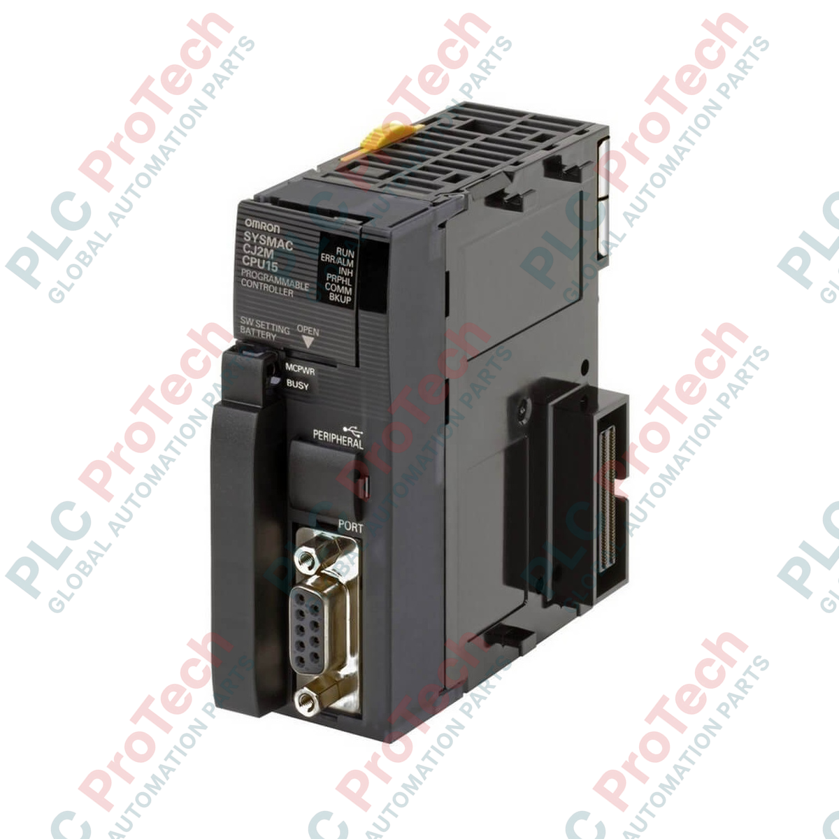
Description
Engineered for high-speed machine control and modular versatility, this Omron CJ2M-CPU15 central processing unit drives automated industrial systems with exceptional processing efficiency. Boasting a substantial 60K steps program capacity and 160K words data memory, this module delivers the memory and speed required for advanced manufacturing, packaging, and sorting architectures. Built-in USB connectivity allows direct diagnostic access, while its physical expandable architecture accommodates high-density digital and analog configurations on a unified backplane bus.
Features
-
High-Speed Execution: Processes basic instructions in 0.04 microseconds for real-time control accuracy.
-
Broad I/O Capacity: Supports up to 2,560 local and expansion I/O points across a maximum of 40 units.
-
Integrated USB Port: Features a high-speed USB 2.0 peripheral port for simple programming and setup using standard cables.
-
Serial Expansion Slot: Built-in slot accepts optional serial communication boards (RS-232C or RS-422A/485) without consuming backplane space.
-
Vast Storage Architecture: Features 60K steps of program space and 160K words of data memory allocation.
Applications
- Automated packaging machinery and high-speed bottling lines.
- Multi-axis pick-and-place gantry systems.
- Water and wastewater municipal treatment monitoring.
- Intralogistics conveyor sorting and distribution hubs.
Technical Specifications
| Parameter |
Specification Value |
| Manufacturer |
Omron |
| Model Code |
CJ2M-CPU15 |
| Product Series |
CJ Series (CJ2M) |
| Program Capacity |
60K steps |
| Data Memory Capacity |
160K words (DM: 32K words, EM: 32K words x 4 banks) |
| LD Instruction Execution Time |
0.04 microseconds |
| Maximum I/O Capacity |
2,560 points (up to 40 expansion units) |
| Current Consumption |
0.50 A at 5 VDC |
| Built-in Interfaces |
USB 2.0 (Type-B) peripheral port |
| Expansion Slots |
1 Serial Option Board Slot |
| Country of Origin |
Japan |
| Shipping Weight (Calculated) |
0.35 kg |
| Package Dimensions (Calculated) |
150 mm x 120 mm x 90 mm |
Connections and Interfaces
| Port / Slot |
Connector Type |
Function / Circuit Assignment |
| Peripheral Port |
USB 2.0 Type-B |
Direct tool bus interface for programming, commissioning, and system parameter backup. |
| Option Slot |
Specialty Connector |
Accepts RS-232C, RS-422A/485, or Ethernet cards for serial telemetry or SCADA interfaces. |
| System Bus |
CJ-Series Backplane Connector |
Distributes internal 5 VDC system power and links the processor to contiguous I/O modules. |
Empirical Engineering Insights
Alternative Models & Compatibility
The CJ2M-CPU15 directly replaces legacy CJ1M series processors, matching physical footprint alignments and mounting rails. However, unlike the CJ2M-CPU3x range, the CPU1x units do not feature an on-board EtherNet/IP port. To integrate Ethernet communication, developers must mount a CJ1W-EIP21 module on the backplane or install a dedicated network option board in the module slot.
Application Pitfalls & Engineering Notes
Pay strict attention to the 5 VDC backplane current budget. The CJ2M-CPU15 draws 0.50 Amps from the system power supply unit. Combining this CPU with multiple high-density communication modules or analog conversion units on the same rack can saturate the main power supply (such as the CJ1W-PA202), causing intermittent hardware resets or execution glitches.
Commissioning & Wiring Tips
To prevent electrical noise issues during high-frequency data logging or programming, use high-quality, double-shielded USB 2.0 cables under 3 meters in length. Ensure the functional ground (FG) terminal on the rack power supply is connected directly to a dedicated low-impedance ground point (100 ohms or less) to eliminate common-mode ground loop noise.
Installation Guidelines
CRITICAL WARNING
Isolate and lock out all upstream power sources supplying the PLC rack assembly prior to installing or extracting this CPU module. Performing hot swaps on the backplane system bus can cause immediate physical damage to the internal logic components, resulting in permanent processor failure.
1
Hook the upper hook of the CJ2M-CPU15 onto the DIN track mounting channel.
2
Align the backplane connector precisely and press the module down until the lower lock clicks securely into position.
3
Secure the unit in place by sliding the yellow interlocking pins on both sides of the adjacent module into the processor slot.
4
Install the terminal end-cover on the last rack module to terminate the system bus and complete the circuit loop.