Description
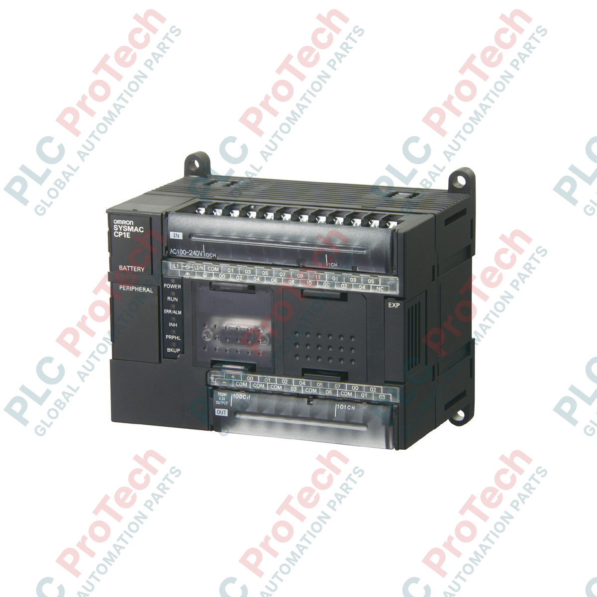
Execution of standard industrial control sequences is efficiently handled by the Omron CP1E-N60DR-A controller, a high-density processing unit from the CP1E family optimized for compact automation tasks. Built with 36 DC inputs and 24 relay outputs, this controller delivers integrated processing capability for applications requiring dependable direct-switching control. It operates on a universal 100 to 240 VAC power supply and features built-in communication interfaces, including an RS-232C port and a USB 2.0 port for diagnostic and programming operations, minimizing the need for external interface modules.
Key Features
-
60 Digital I/O Points: Engineered with 36 24VDC inputs and 24 electro-mechanical relay outputs for direct load switching.
-
Integrated Communication: Includes a standard USB programming port and an RS-232C serial port for HMI or auxiliary device connectivity.
-
Expansibility: Connects up to three CP1W series expansion I/O blocks to accommodate system scaling.
-
Broad Input Compatibility: Supports high-speed counter inputs (up to 100 kHz) for feedback devices like encoders.
-
Robust Memory Allocation: Features an 8K-step program capacity and 8K-word data memory block for complex sequential instructions.
Applications
- Small-to-medium packaging machinery automation.
- Conveyor system speed regulation and path routing.
- Pumping control panels and level-switch management.
- Pick-and-place material handling equipment.
Technical Specifications
| Parameter |
Specification Value |
| Manufacturer |
Omron |
| Model Number |
CP1E-N60DR-A |
| Series |
CP1E (N-Type Application Model) |
| Supply Voltage |
100 to 240 VAC (50/60 Hz) |
| Operating Voltage Range |
85 to 264 VAC |
| Total Input Channels |
36 points (24 VDC) |
| Total Output Channels |
24 points (Relay outputs) |
| Program Memory |
8K steps |
| Data Memory |
8K words |
| Communication Ports |
1x USB 2.0 (Type B), 1x RS-232C |
| Operating Temperature |
0 to 55 degC |
| Physical Dimensions |
195 mm x 90 mm x 85 mm |
| Net Weight |
0.85 kg |
| Shipping Weight (Calculated) |
2.0 kg |
Empirical Engineering Insights
Alternative Models & Compatibility
When migrating legacy systems or replacing obsolete CP1E models, ensure that standard 'E-type' basic CPU units are not accidentally substituted for the CP1E-N60DR-A 'N-type' application variant. The N-type unit features built-in RS-232C ports and high-speed inputs which are critical if your system relies on serial HMI links or encoder-based positioning. If upgrading to the newer CP2E series, the CP2E-N60DR-A is a direct mechanical and logical migration path, but the program must be recompiled inside CX-Programmer to target the new hardware target.
Application Pitfalls & Engineering Notes
To maintain proper thermal convection, this CPU unit must be mounted vertically on a standard DIN rail. Horizontal orientation significantly reduces the thermal limits of the unit, potentially leading to premature diagnostic faults in high ambient enclosure temperatures exceeding 45 degC. Additionally, ensure that inductive relay loads are equipped with external surge suppressors (diode for DC, RC snubber for AC) to avoid inductive kickback from degrading or welding the internal output contacts.
Commissioning & Wiring Tips
The functional ground terminal (GR) must be wired directly to a dedicated low-impedance earth ground path. Sharing a ground conductor with high-noise devices like Variable Frequency Drives (VFDs) can introduce serial bus errors and cause communication drops on the RS-232C port. Always use shielded twisted-pair cabling for all external communication interfaces, bonding the shield only at the master controller end.
Installation Guidelines
CRITICAL SAFETY WARNING
Isolate and lock out all 100 to 240 VAC primary supply power before performing any mounting, wiring, or expansion module integration. Hazardous voltages are exposed at the upper terminal block. Verify that the terminal cover is securely clicked into place before energizing the system.
1
Mount the CPU module securely onto a clean, unpainted 35mm DIN rail, ensuring the top and bottom ventilation spacing guidelines are maintained (minimum 50mm clearance).
2
Connect the 100 to 240 VAC power source to the designated L1 and L2/N terminals using 14-22 AWG copper wire rated for industrial service.
3
Wire input and output control loops ensuring proper polarity for the 24VDC sensor supplies, keeping signal wires isolated from main power cabling routes.