Description
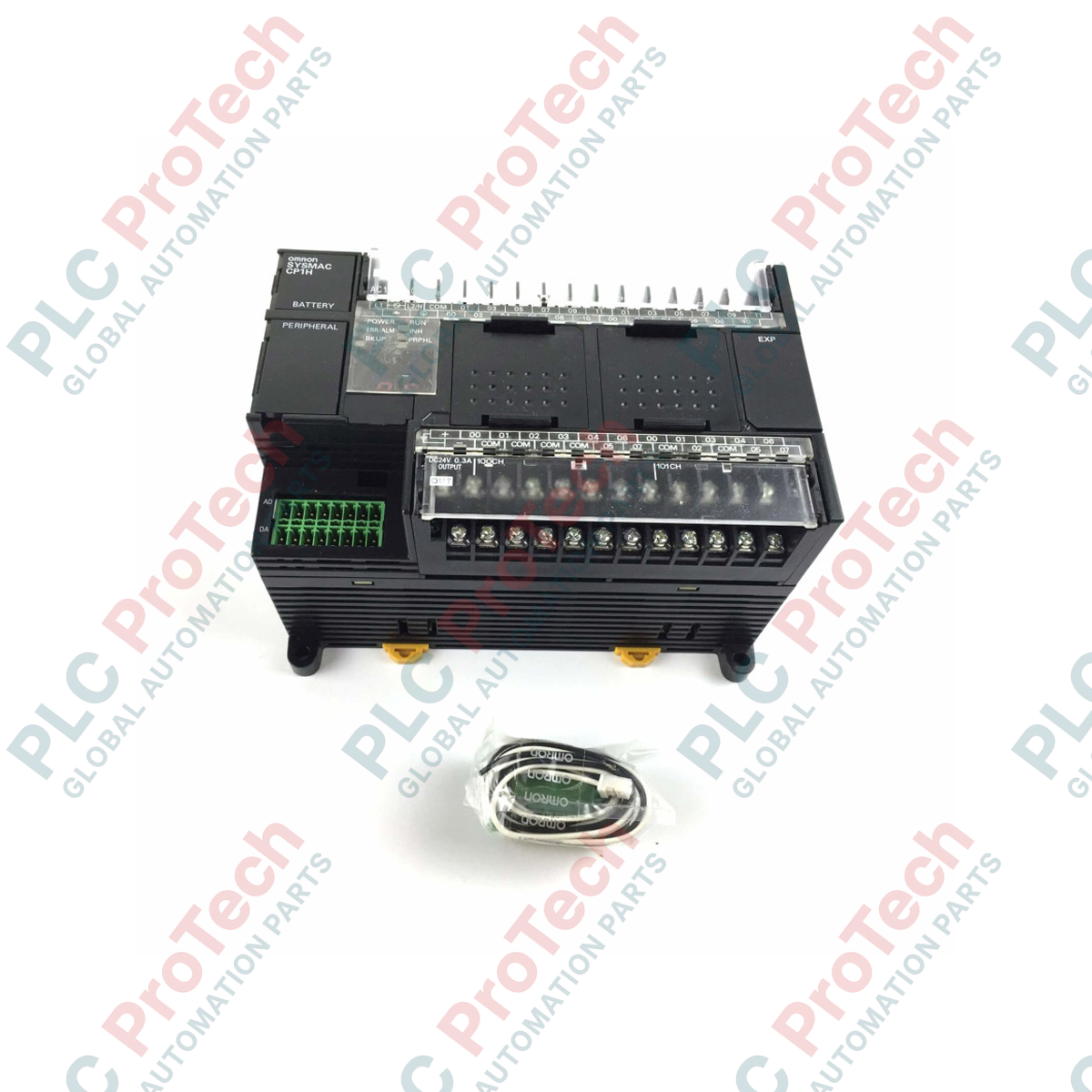
Executing complex automation tasks requires a consolidated controller, which is why the Omron CP1H-XA40DR-A micro PLC excels by integrating high-speed digital processing and high-resolution analog I/O within a single compact footprint. This advanced CPU unit is designed to streamline control architectures by eliminating the need for external analog expansion modules. Operating on AC power, it delivers versatile performance for applications requiring precise analog measurement alongside robust digital control.
Features
-
All-in-One Control: Combines digital I/O, analog I/O, and high-speed counter functions in a single CPU housing.
-
High-Resolution Analog: Features 4 built-in analog inputs and 2 analog outputs with a resolution of 1/12,000.
-
Robust Output Capability: Equipped with 16 electromagnetic relay outputs for direct switching of field actuators.
-
High-Speed Processing: Supports 4 axes of high-speed counters at 100 kHz for high-precision positioning or frequency measurements.
-
Expandable Architecture: Compatible with CP-series expansion units and CJ-series special I/O units for system scaling.
Applications
-
Packaging Machinery: Precise tension control and product positioning using integrated high-speed counters and analog feedback.
-
Water Treatment Facilities: Monitoring chemical dosing pumps and flow rates via built-in 4-20mA/0-10V analog channels.
-
Material Handling Systems: Controlling variable frequency drives (VFDs) and conveyor sorting mechanisms.
-
Environmental Control Chambers: Executing PID temperature loops using integrated analog temperature inputs and relay control outputs.
Technical Specifications
| Parameter |
Specification |
| Manufacturer |
Omron |
| Model |
CP1H-XA40DR-A |
| Series |
CP1H |
| Supply Voltage |
100 to 240 VAC, 50/60 Hz |
| Total Built-In I/O Points |
40 points (24 Inputs, 16 Outputs) |
| Input Type |
24 VDC (Sink/Source) |
| Output Type |
Relay outputs (2 A max per point) |
| Built-In Analog Inputs |
4 inputs (0 to 5V, 1 to 5V, 0 to 10V, -10 to 10V, 0 to 20mA, 4 to 20mA) |
| Built-In Analog Outputs |
2 outputs (0 to 5V, 1 to 5V, 0 to 10V, -10 to 10V, 0 to 20mA, 4 to 20mA) |
| Program Capacity |
20K steps |
| Data Memory Capacity |
32K words |
| High-Speed Counters |
4 axes, 100 kHz (differential/single-phase) |
| Communication Interface |
USB 1.1 (Type B), expandable with up to 2 option boards (RS-232C, RS-422A/485, Ethernet) |
| Shipping Weight (Calculated) |
2.0 kg |
Empirical Engineering Insights
Alternative Models & Compatibility
The CP1H-XA40DR-A belongs to the high-performance XA class, which features built-in analog I/O. If your application requires high-speed pulse outputs for servo/stepper control, you must select the transistor-output variant (CP1H-XA40DT-D) instead, as the relay contacts on this DR-A model cannot execute high-speed pulse output. When replacing older CPM2A series controllers, program conversion can be executed via CX-Programmer, though analog scale values must be remapped to match the 1/12,000 resolution of the CP1H.
Application Pitfalls & Engineering Notes
Because this CPU utilizes mechanical relays for its 16 digital outputs, high-frequency switching should be avoided to prevent premature contact wear. When switching highly inductive AC loads (such as solenoids or contactors), install an external RC snubber circuit across the contacts. For DC inductive loads, use a flyback diode. Maintain standard vertical mounting orientation to ensure natural convection cooling; the ambient operational temperature must remain below 55 degC.
Commissioning & Wiring Tips
The analog inputs and outputs are software-configured using CX-Programmer. Ensure that analog DIP switches located behind the front expansion cover are correctly configured for current (mA) or voltage (V) modes before powering up the unit. Always use twisted, shielded pair cabling for all analog signals and connect the shield to a single functional ground point to prevent ground loop noise from corrupting analog conversion values.
Installation Guidelines
CRITICAL WARNING
Disconnect all AC power sources from the main supply panel before performing any wiring, mounting, or maintenance on the CP1H unit. Failure to completely de-energize the system may lead to severe electrical shock, hardware failure, or unexpected machine activation.
1
DIN Rail Mount
Mount the CPU securely to a standard 35mm DIN rail, ensuring the unit's locking clips snap completely into position to prevent vibration displacement.
2
Power Connection
Wire the L1 and L2/N terminals to a stable 100-240 VAC source. Ensure the functional ground terminal (GR) is connected to a dedicated panel ground wire (100 ohms or less resistance).
3
Analog Configuration
Set the analog input DIP switches based on whether voltage or current signals are connected, then route signal wiring away from high-voltage motor cables.