Description
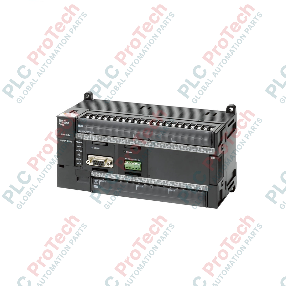
Optimized for complex machine sequencing, the Omron CP1L-M60DR-D is a high-density programmable logic controller within the Sysmac CP1L family. Engineered with 60 built-in discrete I/O points, this DC-powered controller delivers fast task execution and reliable communication expansion options. This controller provides high-speed pulse inputs for multi-axis position monitoring, while its robust relay outputs facilitate direct load switching. The integrated USB peripheral port simplifies commissioning, making this unit a reliable core processor for modern distributed control architectures.
Key Features
-
High-Density Discrete I/O: Out-of-the-box configuration featuring 36 DC inputs and 24 robust relay outputs.
-
Advanced Motion Tracking: Features 4 high-speed encoder counter inputs operating up to 100 kHz for precise position tracking.
-
Modular Hardware Expansion: Supports up to 3 CP-series expansion units to scale system capacity up to 180 local I/O points.
-
Generous Memory Architecture: Features a 10K step program capacity paired with a 32K word Data Memory (DM) block.
-
Universal Compatibility: Programmed with industry-standard CX-Programmer software supporting structured text and ladder logic.
Applications
- High-speed packaging and labeling machinery synchronization.
- Distributed material handling systems and intelligent conveyor lines.
- Multi-axis machine tool positioning and indexing.
- Municipal pumping stations and specialized wastewater treatment systems.
Technical Specifications
| Parameter |
Specification Values |
| Manufacturer |
Omron |
| Model Code |
CP1L-M60DR-D |
| Supply Voltage Range |
20.4 to 26.4 VDC |
| Power Consumption |
20 W maximum |
| Integrated Inputs |
36 inputs (24 VDC, typical input current 4.1 mA) |
| Integrated Outputs |
24 outputs (Relay contacts, 2 A max per point) |
| Program Capacity |
10K steps |
| Data Memory Capacity |
32K words (DM Area) |
| High-Speed Counters |
4 axes (Single phase 100 kHz, differential phases 50 kHz) |
| Operating Temperature |
0 to 55 degC |
| Shipping Weight (Calculated) |
1.1 kg |
| Package Dimensions (Calculated) |
160 mm x 125 mm x 95 mm |
Connections and Interfaces
| Terminal / Port Block |
Electrical & Interface Assignment |
| L+, L-, GR |
24 VDC Power Supply connection terminals with Ground point |
| CIO 0 / CIO 1 Terminals |
Discrete 24 VDC inputs, including high-speed counter channels (0.00 to 0.03) |
| CIO 100 / CIO 101 Terminals |
Relay output contact groups (divided into 1-point and 4-point common groupings) |
| USB Port |
USB 2.0 B-type port for commissioning, programming, and local diagnostics |
Empirical Engineering Insights
Alternative Models & Compatibility
The CP1L-M60DR-D operates strictly on DC power (24 VDC). If your system architecture utilizes standard utility lines, opt for the AC-powered sister unit, the CP1L-M60DR-A. Upgrading CPM1A or CPM2A installations to this platform requires careful evaluation of terminal block terminal positioning, but existing functional ladder structures can be imported into CX-Programmer using automated conversion tools.
Application Pitfalls & Engineering Notes
Because this CPU integrates mechanical relay outputs, rapid cycle-rate switching will significantly shorten the operating life of the contacts. For applications requiring high-frequency pulse-width modulation (PWM) or rapid duty cycles, utilize transistor output models such as the CP1L-M60DT-D. Always use a suppression diode in parallel with external inductive DC loads to mitigate contact damage caused by inductive flyback voltage.
Commissioning & Wiring Tips
The high-speed encoder input terminals are highly susceptible to electromagnetic interference. Route your physical encoder signal wiring away from high-power AC lines and variable frequency drive (VFD) output cables. Ground the cable shield exclusively at the controller-side Ground terminal (GR) to prevent ground loops that disrupt pulse count readings.
Installation Guidelines
CRITICAL SAFETY WARNING
Always isolate the auxiliary power feeding system before wiring the inputs or output circuits. Ensure that the polarity of the 24 VDC power supply to the L+ and L- terminals is verified prior to commissioning. Reverse voltage connections will cause severe hardware damage to the internal logic circuitry.
1
Mount the controller onto a standard 35 mm symmetric DIN rail. Ensure there is at least 50 mm of vertical clearance above and below the housing to facilitate sufficient thermal convection.
2
Connect the 24 VDC control power lines to the L+ and L- terminals using crimped bootlace ferrules. Fasten terminal screws to a maximum torque of 0.5 Nm.
3
Connect the Functional Ground (GR) terminal directly to a low-resistance copper grounding rod within your control cabinet to stabilize reference potentials.