Description
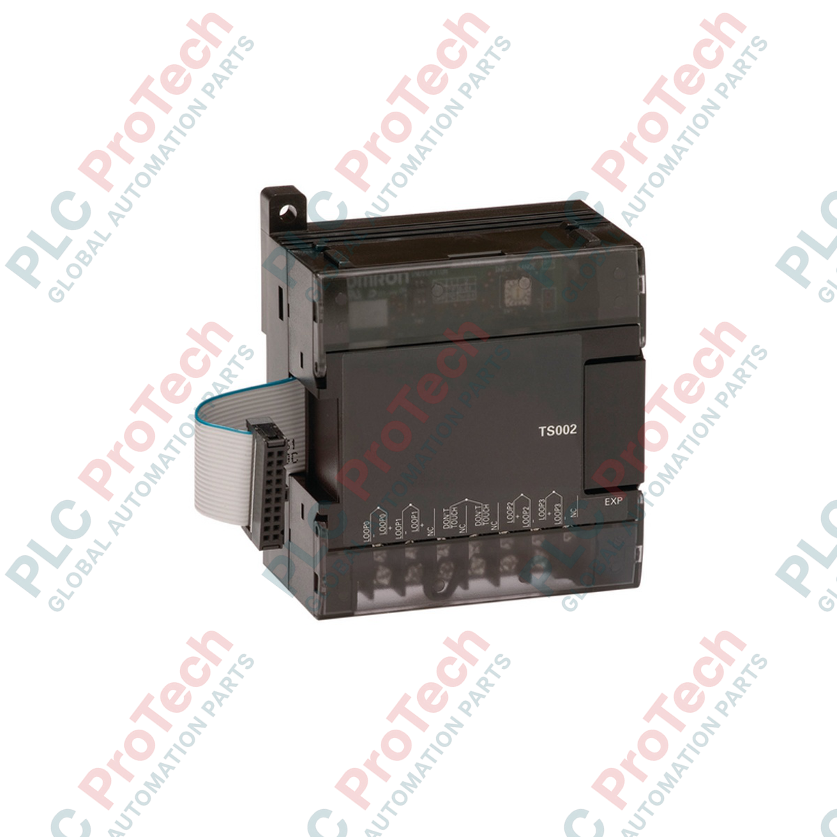
Designed for direct integration with Omron CP-series PLC architectures, the Omron CP1W-TS002 temperature sensor expansion unit expands system capability by providing dedicated high-accuracy thermocouple measurement channels. This module interfaces directly with CP1H, CP1L, and CP1E CPU units, enabling precise thermal monitoring without requiring external signal transmitters. The unit supports up to four thermocouple inputs, which can be configured for either Type K or Type J sensors to meet specific application requirements. Featuring reliable galvanic isolation via photocouplers between input channels and internal PLC logic, the unit ensures stable operation and high noise immunity in demanding electrical environments.
Key Features
-
Four Dedicated Inputs: Supports up to four thermocouple channels on a single expansion slot.
-
Selectable Sensor Types: Field-switchable between Type K and Type J thermocouple inputs.
-
High-Speed Conversion: Complete sampling conversion cycle of 250 milliseconds for active channels.
-
Electrical Isolation: Integrated photocouplers shield the internal logic from field-side electrical surges and ground loops.
-
16-Bit Resolution: Converts thermal data into precise 16-bit binary values (4-digit hexadecimal format).
Applications
- Plastic extrusion and injection molding barrel temperature regulation.
- Industrial heat treatment furnaces and packaging sealing-jaw control.
- Environmental chambers and climate control system integration.
- Food processing and baking oven thermal profile monitoring.
Technical Specifications
| Parameter |
Specification Details |
| Manufacturer |
Omron |
| Model Number |
CP1W-TS002 |
| Module Type |
Temperature Sensor Input Unit |
| Input Type |
Thermocouple (Type K or Type J, switchable) |
| Number of Inputs |
4 channels |
| Allocated Input Words |
4 words |
| Conversion Time |
250 ms for 2 or 4 points |
| Data Format |
16-bit binary data (4-digit hexadecimal) |
| Isolation Method |
Photocouplers between all temperature inputs and internal circuits |
| Current Consumption |
5 VDC at 40 mA maximum; 24 VDC at 59 mA maximum |
| Country of Origin |
Japan |
| Shipping Weight (Calculated) |
0.38 kg |
| Package Dimensions (Calculated) |
110 mm x 90 mm x 80 mm |
Empirical Engineering Insights
Alternative Models & Compatibility
The CP1W-TS002 replaces the lower-density CP1W-TS001 (which supports only two inputs) in systems requiring scale expansions. It fits seamlessly on the right side of any CP1H, CP1L, or CP1E CPU module. Note that CP-series expansion units are not compatible with older C200H or CJ-series backplanes.
Application Pitfalls & Engineering Notes
All four input channels must use the same thermocouple type (either all Type K or all Type J). Mixing sensor types on a single CP1W-TS002 module is not supported and will result in incorrect conversion values. Unused inputs should be configured or physically wired to avoid open-circuit fault flags in the PLC error log.
Commissioning & Wiring Tips
Sensor type selection is managed via DIP switches located beneath the module's protective terminal cover. These hardware configurations must be set while the PLC system is completely powered down. The CPU will not register DIP switch state modifications made during active run-time operations.
Installation Guidelines
CRITICAL WARNING: Ensure all primary and auxiliary power sources feeding the PLC rack are fully de-energized before mounting, removing, or wiring the CP1W-TS002. Working on live equipment risks severe hardware damage, sensor degradation, or unexpected control system behavior.
1
Configure the DIP switch located under the module cover to choose either Type K or Type J thermocouple matching your physical field sensors.
2
Align and secure the expansion bus connector of the CP1W-TS002 to the expansion port on the CPU unit or preceding expansion module.
3
Connect thermocouple lead wires or compensating cables to the designated screw terminals. Keep sensor wires separate from high-voltage AC cables to minimize electromagnetic interference.
4
Power up the PLC system and verify the allocation status using CX-Programmer software to ensure correct input word reading.