Description
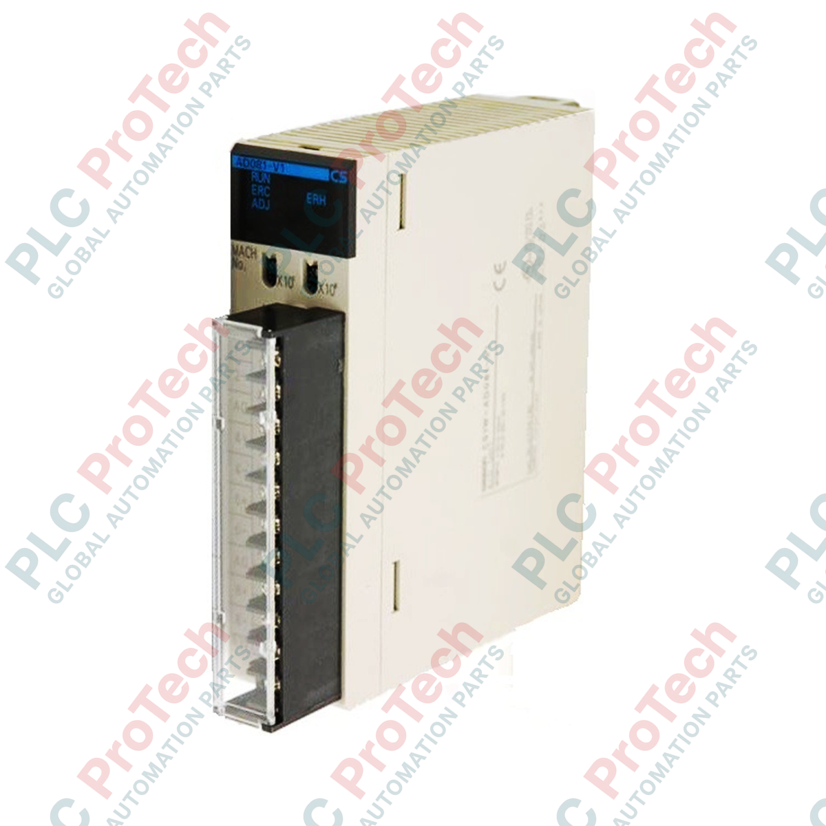
Designed for seamless integration into Sysmac CS-Series PLC backplanes, the Omron CS1W-AD081-V1 Analog Input Unit provides high-density, multi-channel analog-to-digital signal conversion. This Special I/O Unit supports 8 independent analog input channels, allowing direct connection to industrial sensors, transmitters, and flowmeters. Each channel can be configured individually for diverse signal ranges, ensuring maximum system flexibility without requiring dedicated signal conditioning hardware. The module offers selectable high-resolution conversion profiles and robust noise-filtering parameters to deliver clean, reliable process variables to the CPU rack.
Key Features
-
Individual Channel Configuration: Select voltage or current input ranges independently for each of the 8 channels.
-
Selectable Resolution: Configurable conversion resolutions of 1/8,000 or 1/4,000 to match process accuracy requirements.
-
High-Speed Conversion: Operates at a conversion speed of up to 250 microseconds per point (settable to 1 millisecond per point).
-
Detachable Connections: Includes a 21-point detachable M3 screw terminal block for efficient field wiring and rapid module replacement.
-
Peak Hold Function: Stores maximum conversion values during high-speed transient monitoring cycles.
Applications
- Chemical processing and multi-zone temperature logging.
- Flow rate, hydraulic pressure, and level monitoring in water treatment infrastructure.
- Pumping station control loops utilizing 4 to 20 mA feedback transmitters.
- Factory automation and process integration on Sysmac CS1G, CS1H, and CS1D control platforms.
Technical Specifications
| Parameter |
Specification |
| Manufacturer |
Omron |
| Model Number |
CS1W-AD081-V1 |
| Unit Type |
CS-Series Special I/O Unit |
| Number of Analog Inputs |
8 inputs (non-isolated between channels, isolated from PLC bus) |
| Input Signal Ranges (Voltage) |
1 to 5 V, 0 to 5 V, 0 to 10 V, -10 to +10 V |
| Input Signal Ranges (Current) |
4 to 20 mA |
| Conversion Resolution |
1/8,000 (settable to 1/4,000 via DM parameters) |
| Conversion Speed |
250 microseconds/point max. (settable to 1 ms/point) |
| External Wiring Terminals |
21-point detachable terminal block (M3 self-raising screws) |
| Internal Power Consumption |
120 mA max. at 5 VDC, 90 mA max. at 26 VDC |
| Operating Temperature |
0 to 55 degC |
| Country of Origin |
Japan |
| Shipping Weight (Calculated) |
3.0 kg (including shipping protection and original OEM box) |
| Package Dimensions (Calculated) |
155 x 135 x 45 mm |
Empirical Engineering Insights
Alternative Models & Compatibility
The CS1W-AD081-V1 is a direct replacement for the legacy, non-V1 CS1W-AD081 module. The "V1" suffix indicates enhanced internal filtering capabilities and optimized CPU bus communication protocols. When migrating older applications to this V1 hardware, ensure that your CX-Programmer I/O table is updated to reflect the V1 designation to prevent configuration mismatch faults (H-type I/O errors) during hardware download cycles.
Application Pitfalls & Engineering Notes
Note that the channels on the CS1W-AD081-V1 are isolated from the internal PLC logic bus, but are not isolated from channel to channel. They share a common ground line (COM). If you connect field transmitters that have differing ground potentials or use active loop-powered transmitters without 3-way isolation barriers, ground loops will occur. This will distort analog readings and could potentially damage the module's multiplexer circuitry. If channel-to-channel isolation is a project requirement, you must use external isolation signal converters or step up to a fully isolated analog module series.
Commissioning & Wiring Tips
To configure a channel for a 4 to 20 mA current input, you must bridge the voltage input terminal (V IN) with the current input terminal (I IN) using a jumper wire on the detachable terminal block. This short engages the internal precision 250-ohm shunt resistor. Failure to bridge these terminals when selecting current mode in the software configuration will result in an input out-of-range flag. Shielded twisted-pair cables are mandatory for all analog runs, and shields should be grounded at a single, clean grounding point (GR terminal) on the PLC panel side.
Installation Guidelines
CRITICAL WARNING
Always completely de-energize the PLC rack, CPU, and all external power supplies connected to field devices before mounting or removing the analog input module or detach/attach the M3 terminal block. Performing hot-swapping procedures will cause irreparable damage to the internal bus transceiver logic and will immediately void the manufacturer warranty.
1
Configure Unit Number: Set the two rotary switches on the front panel of the CS1W-AD081-V1 to select the desired unit number (MACH No.) within the allowable range (0 to 95). Ensure this does not conflict with existing special I/O units on the same bus.
2
Mount Unit to Backplane: Align the bottom hook of the module with the slot on the backplane, and swing the module upward until it seats firmly. Secure the top mounting screw to ensure robust grounding and mechanical connection.
3
Wire Field Signals: Connect the field sensor leads to the detachable 21-point terminal block. For current inputs, verify the V IN and I IN shorting jumper is securely installed. Tighten all M3 terminal screws to 0.5 N-m torque.
4
Software Parameters Download: In CX-Programmer, open the IO Table, register the module, and access the "Special I/O Unit Settings" to enable each channel, select range values, and specify conversion speed before executing a CPU download.