Description
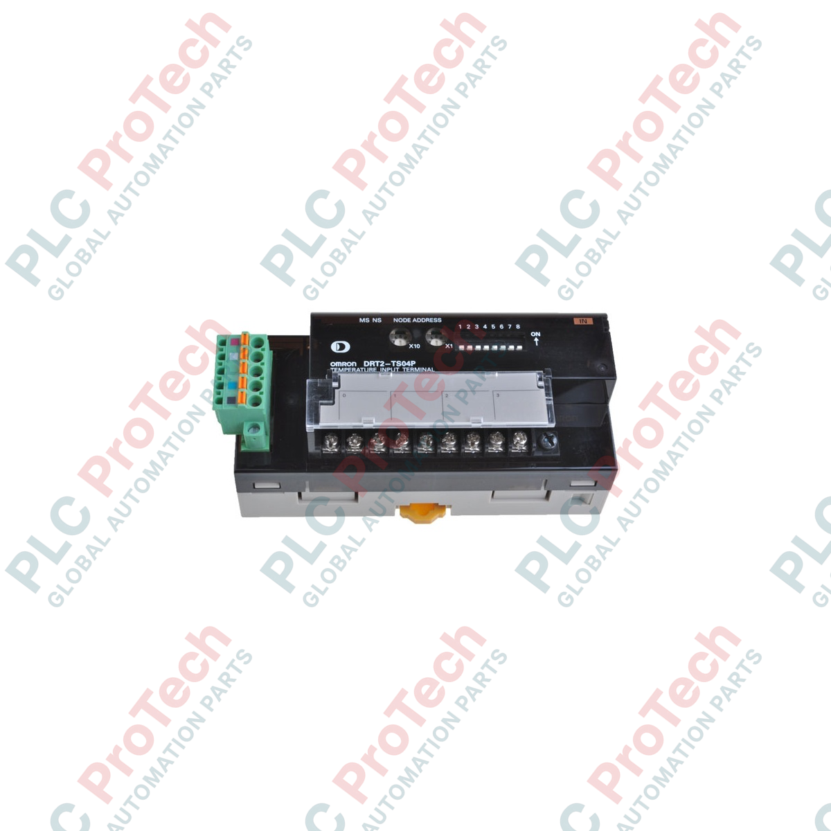
Integrating seamless temperature monitoring into DeviceNet networks, the Omron DRT2-TS04P functions as a high-precision 4-point platinum-resistance thermometer input terminal. This Smart Slave module enables direct digital conversion of analog RTD sensor values right at the process location, transmitting temperature metrics directly to the master controller over the fieldbus network. By utilizing advanced diagnostics, the Omron DRT2-TS04P actively tracks communications voltage thresholds, operating times, and sensor break status, helping operators maintain peak uptime across modern industrial processing lines.
Key Features
-
Multi-Channel RTD Support: Interfaces up to 4 channels of standard platinum-resistance thermometers (Pt100 or JPt100).
-
Scalable I/O Allocation: Selectable display resolution modes allocate either 4 input words (1/10 display mode) or 8 input words (1/100 display mode) on the DeviceNet network.
-
Built-In Smart Functionality: Real-time monitoring of communication power supply levels, run-time hours, and internal sensor status.
-
DeviceNet Native Bus-Power: Runs directly off the 11 to 25 VDC DeviceNet trunk line, reducing localized control-panel wiring.
-
DIP Switch Configuration: Simple on-device dip switches facilitate rapid physical network address assignment and input type definition.
Applications
- Precision heating zones in plastics extrusion machinery and thermoforming units.
- Multi-zone temperature tracking in commercial baking and pasteurization tunnels.
- Climate and environmental controls within pharmaceutical manufacturing cleanrooms.
- Cold-storage facility logging and cooling circuit status monitoring.
Technical Specifications
| Parameter |
Specification |
| Manufacturer |
Omron |
| Model Number |
DRT2-TS04P |
| Input Types |
Pt100, JPt100 (Platinum-resistance thermometers) |
| Number of Inputs |
4 analog RTD channels |
| Network Comm. Power |
11 to 25 VDC (from DeviceNet network cable) |
| Current Consumption |
70 mA maximum at 24 VDC; 110 mA maximum at 11 VDC |
| Display Resolution Modes |
1/10 display mode (4 words); 1/100 display mode (8 words) |
| Operating Temperature |
-10 to 55 Celsius |
| Storage Temperature |
-25 to 65 Celsius |
| Operating Humidity |
25% to 85% RH (non-condensing) |
| Unit Weight |
0.16 kg |
| Shipping Weight (Calculated) |
0.45 kg |
| Package Dimensions (Calculated) |
130 mm x 110 mm x 85 mm |
Connections and Interfaces
| Terminal Block Pin |
Assigned Function |
| Red Wire (DeviceNet Connector) |
V+ Network Power Supply Line |
| White Wire (DeviceNet Connector) |
CAN High Signal Line |
| Shield (DeviceNet Connector) |
Drain / Shield Line |
| Blue Wire (DeviceNet Connector) |
CAN Low Signal Line |
| Black Wire (DeviceNet Connector) |
V- Network Power Supply Line |
| RTD Input Terminals (CH0 - CH3) |
Three-wire RTD Sensor Connections (A, B, b) per active channel |
Empirical Engineering Insights
Alternative Models & Compatibility
The DRT2-TS04P belongs to the DeviceNet Smart Slave family and replaces legacy DRT1-series temperature blocks. Unlike first-generation terminals, the DRT2 architecture includes expanded EDS (Electronic Data Sheet) capabilities for deeper tool-assisted commissioning via Omron CX-Integrator. Ensure the master module scanner profile has been updated to accommodate the expanded 8-word space when operating in high-resolution (1/100 display) mode to prevent communication cycle overlaps.
Application Pitfalls & Engineering Notes
When routing three-wire platinum resistance thermometers, match the physical resistance of all three lines to preserve high-accuracy compensation. Unequal line impedance in long runs introduces temperature offset errors that cannot be software-corrected. Additionally, operating in 1/100 resolution mode increases network transmission sizes. In saturated DeviceNet networks with multiple drops, this can spike network latency; verify baud rate capacities and physical segment distances accordingly.
Commissioning & Wiring Tips
To minimize high-frequency EMF interference from adjacent high-power lines, run RTD sensor cables inside separate metallic conduits. Always wire the DeviceNet shield line directly to an independent, noise-free functional ground terminal at only one node on the bus. Setting the physical node address (MAC ID) must be done prior to unit initialization by setting the integrated DIP switches; changing DIP switches while the unit is powered will trigger a configuration fault on the DeviceNet Master scanner.
Installation Guidelines
CRITICAL WARNING: De-energize all primary, auxiliary, and network power supplies before mounting, connecting, or servicing the DRT2-TS04P terminal. Failure to do so can lead to electrical shock risks, erratic field bus cycles, or permanent destruction of sensitive internal measurement circuits.
1
Mount the DRT2 terminal securely onto standard 35 mm DIN rail inside a protective, industrial-grade electrical control enclosure (minimum IP20).
2
Configure the hardware rotary address dials and DIP switches to define the assigned node address and input range selection prior to system initialization.
3
Attach the DeviceNet micro-connector block, ensuring matching wire colors corresponding to CAN-H, CAN-L, power lines, and ground lines.
4
Connect the 3-wire RTD sensors to the screw terminals. Torque all wiring terminal connections to the manufacturer recommended limits to prevent thermal drift.