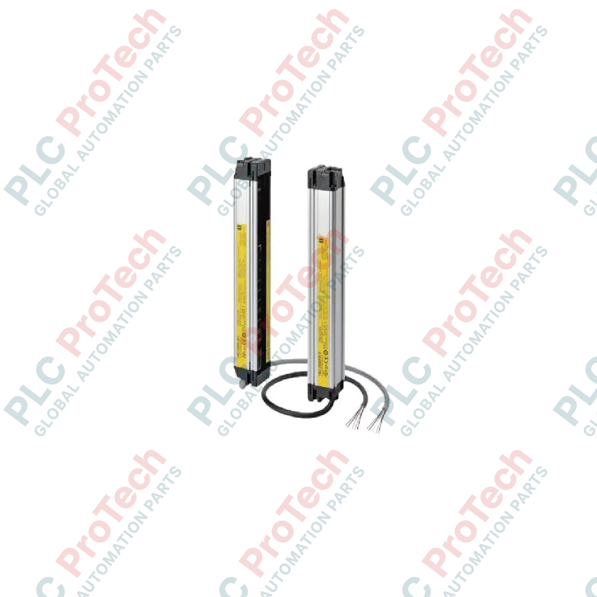
Description
Facilitating hand and arm protection across automated manufacturing cells, the Omron F3SJ-E0225P25 functions as a Type 4 safety light curtain designed for straightforward safety integration. Operating on a 24 VDC SELV/PELV power supply, this optical barrier provides a 225 mm protective height and features 10 light beams with a 20 mm beam gap, optimized to detect objects down to a 25 mm diameter. Its streamlined design simplifies wiring and alignment, making it an excellent fit for space-constrained and hazardous industrial workspaces requiring reliable light-grid monitoring.
Features
-
Type 4 Safety Rating: Designed and certified to meet stringent international machinery safety standards.
-
25 mm Detection Capability: Optimized resolution specifically targetted for hand and arm detection.
-
PNP Outputs: Dual PNP safety semiconductor outputs with short-circuit and reverse polarity protection.
-
Rugged Enclosure: Rated to IP65 to prevent dust ingress and resist low-pressure water jets.
-
Infrared Detection: Utilizes an infrared LED light source operating at an 870 nm wavelength.
Applications
- Robotic assembly workstations and pick-and-place systems.
- Material handling systems, palletizers, and conveyor sorting lines.
- Stamping, forming, and light industrial packaging machinery.
Technical Specifications
| Parameter |
Specification |
| Manufacturer |
Omron |
| Model Number |
F3SJ-E0225P25 |
| Series |
F3SJ-E (Easy Type) |
| Sensor Type |
Type 4 Safety Light Curtain |
| Protective Height |
225 mm |
| Number of Beams |
10 |
| Beam Gap |
20 mm |
| Detection Capability |
25 mm diameter (hand protection) |
| Operating Range |
0.2 to 7.0 m |
| Power Supply Voltage |
24 VDC +/-20% (SELV/PELV, ripple p-p 10% max.) |
| Output Type |
PNP safety outputs (x2) |
| Current Consumption (Emitter) |
41 mA maximum |
| Current Consumption (Receiver) |
42 mA maximum |
| Light Source |
Infrared LED (wavelength 870 nm) |
| Degree of Protection |
IP65 (IEC 60529) |
| Net Weight |
1.1 kg |
| Shipping Weight |
2.0 kg |
Empirical Engineering Insights
Alternative Models & Compatibility
The F3SJ-E (Easy) series is configured for simple ON/OFF safety output functions. Unlike the advanced F3SJ-A series or the configurable F3SJ-B series, the F3SJ-E0225P25 does not support auxiliary programming, muting modules, or series connection (cascading). If your application requires blanking or cascading multiple light curtains, you must upgrade to the F3SJ-B or F3SJ-A equivalents.
Application Pitfalls & Engineering Notes
When positioning the light curtain, ensure that reflective surfaces (such as highly polished stainless steel plates or shiny aluminum guards) are placed outside the reflective boundary zone. Highly reflective surfaces can deflect the infrared beam around an obstructing object, preventing the receiver from detecting an intrusion and compromising the safety system's integrity.
Commissioning & Alignment Tips
The F3SJ-E features built-in LED alignment indicators on the face of both the emitter and receiver. During commissioning, if the alignment is imperfect, the status indicators will flash red or yellow. Adjust the physical brackets until the green alignment indicator shines steadily, verifying optical path optimization before locking down the mounting hardware.
Installation Guidelines
CRITICAL WARNING
Isolate and lock out all primary and auxiliary power sources before handling, mounting, or wiring the safety light curtain. Verify that no residual electrical charges remain in associated machinery control circuits. Failure to follow industrial de-energization protocols can result in severe physical injury or equipment damage.
1
Position the emitter and receiver units at identical heights on rigid, vibration-resistant mounting structures, ensuring the optics directly face one another.
2
Wire the emitter and receiver using high-quality shielded cables. Ground the shield at the control panel to minimize electromagnetic interference (EMI).
3
Connect the dual PNP outputs directly to a safety relay module or a safety-rated PLC input card. Do not wire safety outputs to standard, non-safety PLCs.
4
Power up the system, verify beam alignment using the integrated LEDs, and conduct a full test-piece interruption test across all 10 beams before starting production.