Description
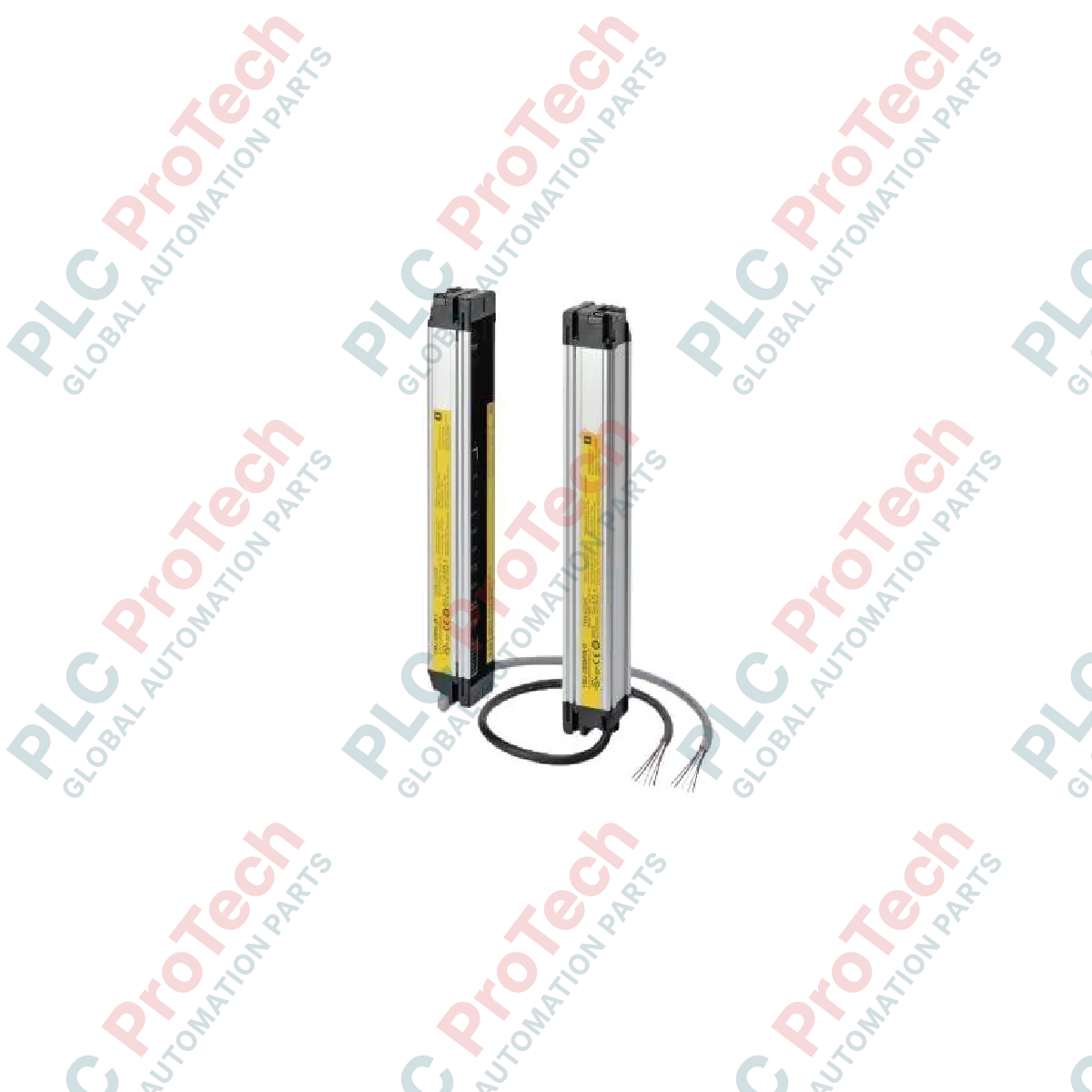
Providing reliable hand protection in heavy industrial environments, the Omron F3SJ-E0625P25 safety light curtain functions as a Type 4 safeguarding sensor with a 625 mm protective height. This optoelectronic guard employs an infrared LED array with a 20 mm beam gap and 25 mm detection capability, making it ideal for detecting hands and arms as they approach hazardous machinery. Designed with simple PNP outputs and a pre-configured, non-complex functional profile (Easy Type), this unit integrates directly into safety PLC or safety relay circuits without requiring complex software setups.
Features
-
Type 4 Safety Sensor: Meets rigorous global functional safety standards for PL e (ISO 13849-1) and SIL3 (IEC 61508) architectures.
-
High-Density Beam Array: Uses 30 optical beams to maintain precise detection resolution across the entire active field.
-
Long Operating Range: Covers scanning distances from 0.2 m up to 7 m, accommodating both compact machine envelopes and wider perimeter entries.
-
Robust Environmental Sealing: Rated to IP65, providing defense against dust ingress and low-pressure water jets.
-
Simplified Wiring: Features built-in mutual interference prevention to ensure stability when multiple units are mounted in close proximity.
Applications
-
Robotic Workstations: Surrounds automated robotic arms to immediately interrupt operation if an operator breaches the working envelope.
-
Stamping and Power Presses: Protects hand and arm access zones during manual workpiece loading/unloading sequences.
-
Packaging and Conveyor Lines: Safeguards automated sorting and palletizing equipment from accidental human contact.
-
Material Handling Systems: Manages entry-exit zones where hazardous mechanical action must be paused during manual intervention.
Technical Specifications
| Parameter |
Specification |
| Manufacturer |
Omron |
| Model Code |
F3SJ-E0625P25 |
| Sensor Classification |
Type 4 (IEC 61496-1) / Category 4, PL e (EN ISO 13849-1) |
| Protective Height |
625 mm |
| Detection Capability |
25 mm (diameter) |
| Number of Beams |
30 |
| Beam Pitch (Gap) |
20 mm |
| Operating Range |
0.2 m to 7 m |
| Output Type |
2 x PNP semiconductor outputs (OSSD) |
| Power Supply Voltage |
24 VDC +/-20% (SELV/PELV, ripple p-p 10% max.) |
| Current Consumption (Emitter) |
57 mA maximum (30 beams) |
| Current Consumption (Receiver) |
47 mA maximum (30 beams) |
| Light Source (Wavelength) |
Infrared LED (870 nm) |
| Enclosure Protection |
IP65 (IEC 60529) |
| Net Weight |
2.2 kg |
| Shipping Weight (Calculated) |
4.0 kg |
Empirical Engineering Insights
Alternative Models & Compatibility
The F3SJ-E (Easy Type) serves as a streamlined alternative to the F3SJ-A (Advanced) and F3SJ-B (Basic) series. Note that the F3SJ-E features fixed functions and does not support software configurations, auxiliary outputs, or series-connection cascading. If your application demands blanking, muting, or series-linking of multiple curtains, you must transition to the F3SJ-A series, as the F3SJ-E hardware is physically incompatible with these configurations.
Application Pitfalls & Engineering Notes
Because this model utilizes fixed mutual interference prevention, mounting two F3SJ-E pairs back-to-back can cause optical cross-talk if not separated by an opaque physical barrier or oriented with opposing emitter/receiver directions. Ensure the safety distance calculation (S) complies with EN ISO 13855, accounting for the 25 mm resolution (which dictates a minimum intrusion depth factor, d, of 80 mm in the standard calculation formula).
Commissioning & Wiring Tips
Always route the OSSD output cables in separate conduits from high-power AC motor lines and Variable Frequency Drive (VFD) cabling. Inductive coupling on the OSSD feedback loops can trigger intermittent fault codes (flanking red LED diagnostics on the receiver). Ensure the 24 VDC power supply is a dedicated SELV/PELV source to prevent transient voltage spikes from damaging the internal output transistors.
Installation Guidelines
CRITICAL WARNING
De-energize all primary machine power sources before initiating installation. Verify complete absence of residual voltage in control circuits. Failure to lock out electrical and kinetic energy sources during mounting can result in severe physical injury or equipment damage. This safety light curtain must be installed and tested exclusively by qualified automation personnel in strict accordance with local machinery directives.
1
Mounting and Mechanical Alignment: Fix the mounting brackets securely to a rigid frame. Ensure the emitter and receiver are parallel, with both top and bottom edges perfectly aligned. Check that the indicator LEDs are easily visible to the operator.
2
Electrical Connections: Connect the emitter and receiver cables to the control panel. Connect the dual PNP OSSD outputs directly to a safety monitoring relay or safety PLC input card. Do not parallel the two OSSD channels.
3
Optical Verification: Power up the unit and inspect the LEDs on the receiver. Adjust the physical alignment of the heads until the green alignment indicator lights consistently. Ensure no yellow or red diagnostic error states are active.
4
Commissioning Test: Use the standard 25 mm test piece to verify detection at multiple points along the light curtain path. Ensure that interrupting any part of the field immediately switches the safety outputs to the OFF state.