Description
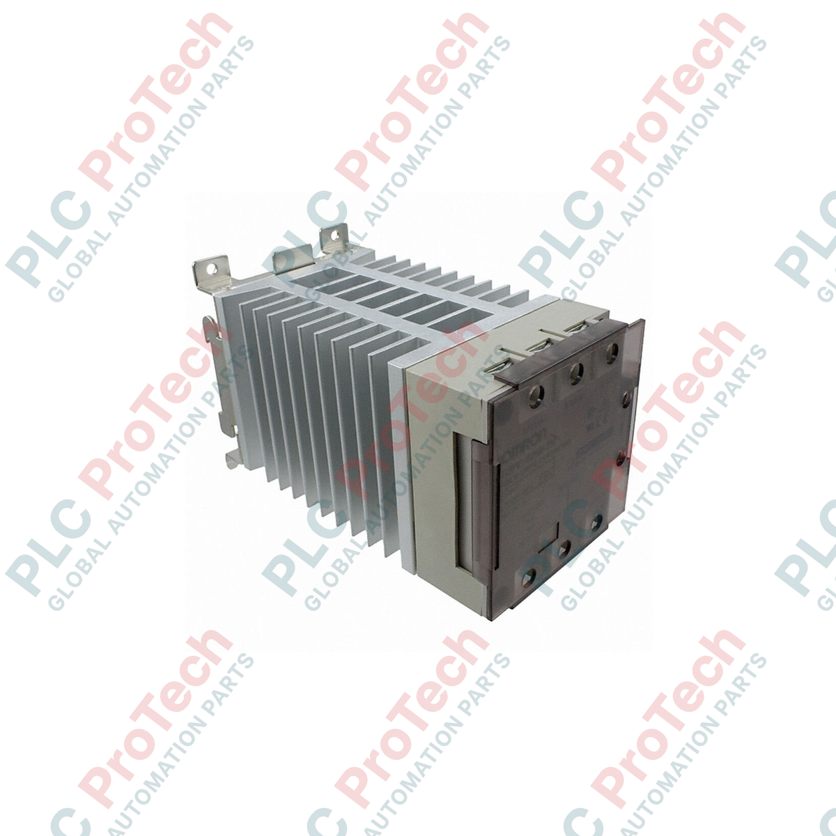
Delivering high-capacity resistive load control for industrial thermal systems, the Omron G3PE-245B-2N provides robust 3-phase solid-state switching within demanding automation networks. This unit is specifically engineered for heating element control, utilizing a phototriac isolation method and an integrated zero-cross function to suppress electromagnetic interference and line noise during switching cycles. Fitted with heavy-duty screw terminals and an integrated heatsink structure, it manages high load currents reliably in high-density panel configurations without physical contact wear.
Features
-
Zero-Cross Control: Minimizes high-frequency noise and surge currents when turning on resistive heating elements.
-
High Isolation Barrier: Built-in phototriac isolation protects delicate low-voltage PLC control circuits from load-side transients.
-
Heavy-Duty Screw Terminals: Optimized physical connection interface ensures reliable contact pressure and low terminal resistance.
-
Robust Inrush Capacity: Features a high inrush current tolerance of up to 440 A to withstand line fluctuations and initial element cold resistance.
Applications
- Industrial molding, curing, and heat-treatment ovens.
- Plastic extrusion lines and injection molding heater bands.
- Semiconductor manufacturing deposition and baking chambers.
- Packaging machinery shrink tunnels and sealing bars.
Technical Specifications
| Parameter |
Value / Specification |
| Manufacturer |
Omron |
| Model Reference |
G3PE-245B-2N |
| Control Input Rated Voltage |
12 to 24 VDC |
| Control Input Operating Range |
9.6 to 30 VDC |
| Maximum Input Current |
10 mA maximum (at 24 VDC) |
| Must-Operate / Must-Release Voltages |
9.6 VDC maximum / 1.0 VDC minimum |
| Rated Load Voltage |
100 to 240 VAC (50/60 Hz) |
| Load Voltage Operating Range |
75 to 264 VAC (50/60 Hz) |
| Rated Load Current |
45 A (at ambient temperature of 40 degC) |
| Minimum Load Current |
0.5 A |
| Inrush Current Resistivity |
440 A (60 Hz, 1 cycle) |
| Permissible I2t Value |
1260 A2s |
| Applicable Load Capacity |
15.5 kW (at 200 VAC) |
| Isolation Method |
Phototriac |
| Zero-Cross Function |
Equipped |
| Connection Method |
Screw Terminals |
| Shipping Weight (Calculated) |
3.0 kg |
Connections and Interfaces
| Terminal / Pin Label |
Function and Wiring Assignment |
| A1 (+) |
Positive Control Input (12 to 24 VDC) |
| A2 (-) |
Negative Control Input (DC Common Ground) |
| L1 / L2 |
3-Phase AC Power Source Supply Lines (Inputs) |
| T1 / T2 |
3-Phase AC Controlled Load Feed Lines (Outputs to Heater) |
| Ground Terminal |
Metal baseplate connection for safety earthing |
Empirical Engineering Insights
Alternative Models & Compatibility
The "2" designation in this module code indicates a 2-line control (3-phase, 2-element) configuration. This configuration controls two phases while passing the third phase directly, making it highly efficient for balanced delta heater networks. It is a drop-in functional replacement for legacy G3PE configurations of equivalent ratings, provided the 12-24 VDC logical signal current threshold can supply a continuous 10 mA.
Application Pitfalls & Engineering Notes
Thermal management is critical when operating at 45 A load currents. Ambient operating temperature within the enclosure must not exceed 40 degC to avoid automatic thermal derating. Ensure the module is mounted vertically with the heatsink fins unobstructed. If installing inside fully enclosed or non-ventilated control panels, derate your maximum load limit by up to 50% or introduce active thermal management (cabinet fans).
Commissioning & Wiring Tips
Always use properly crimped ring or fork terminals on the power lines to prevent stray strands from bridging adjacent terminals. Ensure the screw terminals are torqued down precisely to the manufacturer recommendation of 1.47 to 1.96 N-m. Check and retighten power terminals after the initial 24 hours of operation to correct for thermal settling of the wire.
Installation Guidelines
CRITICAL WARNING: Ensure all 3-phase AC main power supply breakers are isolated, locked out, and tagged before attempting electrical installation or physical service. Always use an appropriately rated voltage tester on all terminals to confirm the absence of power before handling cabling.
1
Mount the unit vertically onto a clean, unpainted segment of 35mm DIN rail, ensuring the heatsink fins run vertically to facilitate natural convective airflow.
2
Connect the safety earth ground terminal directly to the panel main earth bar using copper wire of adequate cross-section (minimum 4 mm2).
3
Wire the DC control inputs (A1 positive, A2 negative) from the PLC sourcing or sinking card using shielded, twisted-pair cables to mitigate nearby induction noise.
4
Route high-current 3-phase AC lines to terminals L1/L2 and load lines to terminals T1/T2, ensuring all terminations are firmly torqued to avoid resistance-induced hot spots.