Description
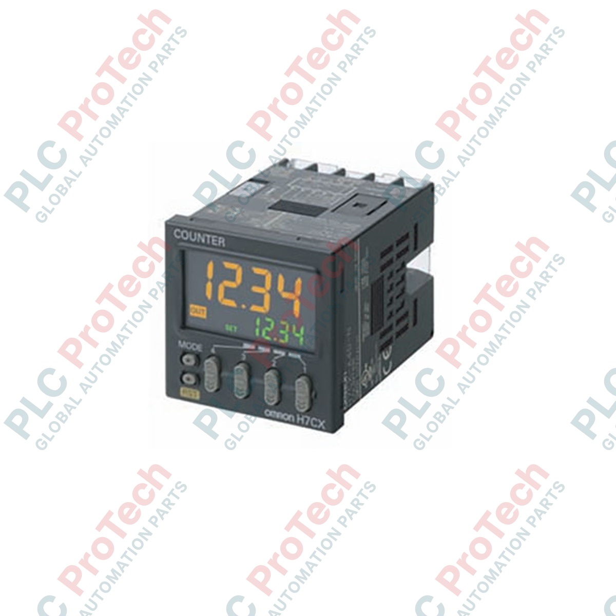
Optimized for dynamic process monitoring, the Omron H7CX-A4S-N acts as a highly reliable industrial counting and rate-measurement module within a standard DIN-sized footprint. This 4-digit, single-stage configuration device serves dual functions as a digital counter and high-speed tachometer, making it ideal for tracking cycles, batch quantities, and rotational velocities. Equipped with screw terminals and a fast-acting transistor output, the unit integrates smoothly into low-latency control loops driven by PLCs or supervisory relays. The integrated power supply accepts universal AC voltage, mitigating the need for external step-down transformers in standard control panels.
Features
- Dual-function layout operational as either an advanced digital counter or precise tachometer.
- High-visibility 4-digit display featuring dynamic, custom-configurable color-changing status backlighting.
- Single-stage preset control providing rapid trigger capability upon reaching target setpoints.
- Solid-state transistor output designed for high-frequency switching operations and spark-free output logic.
- Universal wide-range AC power input supporting global electrical standards.
- Robust rear-facing screw terminals ensuring secure physical connections under structural vibration.
Applications
- High-speed industrial packaging line batch counting and piece tracking.
- Rotational velocity (RPM) measurement and slip detection on heavy conveyor systems.
- Precision length-cutting operations using quadrature encoder input setups.
- Stamping and cycle-limit monitoring for automated metal fabrication machinery.
Technical Specifications Table
| Parameter |
Value |
| Manufacturer |
Omron |
| Model Reference |
H7CX-A4S-N |
| Device Type |
Multifunction Counter / Tachometer |
| Display Digits |
4 digits (-999 to 9999) |
| Supply Voltage |
100 to 240 VAC at 50/60 Hz |
| Preset Stages |
1-stage preset |
| Output Type |
Transistor output (NPN/PNP selectable) |
| Connection Method |
Rear screw terminal block |
| Front Panel Dimensions |
48 mm x 48 mm (1/16 DIN) |
| Insertion Depth |
84 mm |
| External Sensor Power |
12 VDC (up to 100 mA) |
| Shipping Weight (Calculated) |
0.35 kg |
Connections and Interfaces
| Terminal |
Function Description |
| 1 |
AC Power Supply Input (Line) |
| 2 |
AC Power Supply Input (Neutral) |
| 3 |
Sensor Power Supply Output (+12 VDC) |
| 4 |
Signal Input A (Count / Tachometer Pulse Input) |
| 5 |
Signal Input B (Directional Count Control) |
| 6 |
Reset Input Signal (External Counter Clear) |
| 7 |
Key Protect Input (Locks Front Panel Parameters) |
| 8 |
Output Common Ground (0V Reference) |
| 9 |
Transistor Output (Collector) |
Empirical Engineering Insights
Alternative Models & Compatibility
The updated "N" suffix denotes a modernized internal processor design complying with recent RoHS directive updates and enhanced display contrast. The H7CX-A4S-N serves as a direct drop-in replacement for the legacy H7CX-A4S model. When replacing older non-N versions, verify parameter compatibility, as default gate time and input speed profiles may require brief adjustment in the configuration utility menu.
Application Pitfalls & Engineering Notes
When using this module in tachometer mode, avoid routing high-voltage motor lead lines in parallel with the sensor inputs. If physical relay or microswitch contacts are used for inputs instead of proximity sensors, set the maximum input speed setting to 30 Hz via the internal menu. Setting this parameter to 5 kHz or 10 kHz with physical contacts will result in count tracking errors caused by mechanical switch bounce.
Commissioning & Wiring Tips
Always utilize shielded twisted-pair cabling for the sensor inputs (Input A and Input B). To prevent ground loops from injecting electrical noise into the counter's internal processor, ground the cable shield strictly at the single point panel ground instead of tying it back to Terminal 8 (Common).
Installation Guidelines
CRITICAL WARNING
Isolate and lock out all upstream electrical power sources supplying the 100-240 VAC feed lines prior to initiating any installation, modification, or wiring operations. Failure to verify zero-energy states on these contacts presents a severe electrical shock hazard and can cause complete structural destruction of the internal control components.
1
Mount the counter into a standard 45 mm x 45 mm DIN panel cutout, securing the device housing from behind using the native mounting adapter bracket.
2
Route input signals separate from power lines and wire input sensors to Terminals 4 and 5 according to either NPN or PNP operational rules.
3
Connect the transistor output load to Terminals 8 and 9, keeping current load draw below the standard rating to prevent overheating the output stage.
4
Terminate the main 100 to 240 VAC power source wires to Terminals 1 and 2, recheck all structural terminal tightening torques, and energize the system.