Description
Engineered for precise control in high-speed industrial operations, the Omron H7CX-AW-N provides versatile, dual-preset pulse processing capabilities within modern control panels. Integrating advanced counting and tachometer functionalities into a compact, space-saving footprint, this 6-digit multifunction counter supports highly responsive switching cycles. With its robust 12 to 24 VDC electrical architecture and reliable screw terminal connections, it offers seamless integration for factory automation networks requiring strict tracking of batch runs, rotational speed parameters, and process timing.
Features
-
Multifunctional Flexibility: Operates dynamically as a 2-stage counter, twin counter, batch counter, dual counter, or digital tachometer.
-
Dual Contact Outputs: Equipped with SPST-NO and SPDT relay configurations for complex cascading control operations.
-
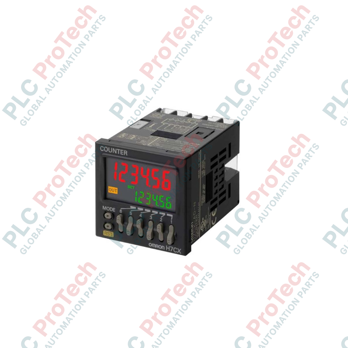
High-Visibility 6-Digit Display: Features a negative transmissive character layout with a dynamic, multi-color backlight showing current status at a glance.
-
Robust Environmental Protection: IP66-rated front panel prevents dust and moisture ingress in harsh washdown zones.
-
Low-Voltage Safety: Optimized for low-voltage industrial control networks utilizing steady 12 to 24 VDC power grids.
Applications
- High-speed batch count operations on packaging and bottling lines.
- Cut-to-length linear positioning and material feed processing systems.
- Rotational speed monitoring and tachometer control on industrial conveyor belts.
- Dual-stage process control loops inside compact power distribution boards.
Technical Specifications
| Specification Category |
Value / Rating |
| Manufacturer |
Omron |
| Model Designation |
H7CX-AW-N |
| Series Class |
H7CX Series |
| Device Type |
Multifunction Digital Counter / Tachometer |
| Display Configuration |
6-digit, 7-segment negative transmissive LCD with backlight |
| Preset Stages |
2-stage control (independent set values) |
| Power Supply Voltage |
12 to 24 VDC (Permissible ripple: 20% max.) |
| Output Type |
Contact output (SPST + SPDT) |
| Connection Method |
Screw terminals (M3.5 finger-safe clamping) |
| Maximum Counting Speed |
Selectable: 30 Hz or 5 kHz (minimum pulse width: 16.7 ms or 0.1 ms) |
| Operating Temperature |
-10 to 55 degC (with no icing or condensation) |
| Net Instrument Weight |
0.130 kg |
| Shipping Weight (Calculated) |
1.000 kg |
| Dimensions (Calculated) |
48 mm x 48 mm x 84 mm (W x H x D) |
Empirical Engineering Insights
Alternative Models & Compatibility
The legacy "-AW" models are direct dimensional equivalents to this updated "-N" suffix device. However, the H7CX-AW-N features an optimized internal microprocessor that shortens processing cycles and improves display update rates. When retrofitting, verify that existing sensor currents do not exceed the auxiliary DC sensor output limits of the updated module.
Application Pitfalls & Engineering Notes
When mounting multiple controllers adjacent to each other on standard DIN panel rails, leave a physical gap of 5 mm between units if the ambient enclosure temperature routinely exceeds 45 degC. Because these controllers operate on solid-state timing circuitry, proximity to high-capacity variable frequency drives (VFDs) without line filters can lead to high-frequency electromagnetic noise causing false pulse registers.
Commissioning & Wiring Tips
Ensure the internal DIP switch or software configuration matches the physical wiring input configuration (NPN/PNP switch selection). If utilizing standard 3-wire proximity sensors, wire the sensor outputs to CP1/CP2 input terminals with shielded, twisted-pair cables to safeguard signal integrity over long-distance cable runs.
Installation Guidelines
CRITICAL WARNING: ELECTRICAL HAZARD
Isolate all primary feed circuits and shut down field power sources prior to working on terminal wiring blocks. Residual DC capacitor charge may remain inside adjacent automation equipment; verify voltage-free status using an industrial-grade multimeter before contacting any electrical terminals.
-
1
Prepare a standard 1/16 DIN panel cutout (dimensions 45 mm x 45 mm) through the target enclosure surface.
-
2
Slide the counter housing into the cutout slot, making sure the external waterproof packing rubber is seated flush.
-
3
Attach the secure mounting bracket from the back of the panel, tightening the screws uniformly until snug.
-
4
Wire signal lines to terminal screws using M3.5 crimp ring terminals, applying a tight terminal torque between 0.5 and 0.6 Nm.