Description
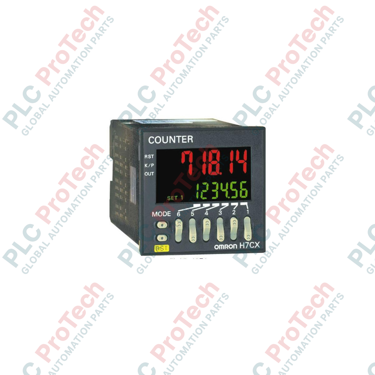
Operating as a dual-preset digital control device, the Omron H7CX-AWD1-N regulates industrial process timing and counting applications across high-speed manufacturing lines. This highly configurable 1/16 DIN instrument functions seamlessly as a 1-stage counter, 2-stage counter, total counter, batch counter, dual counter, or tachometer. Engineered with a negative transmissive LCD display, it provides highly legible process value readouts that dynamically shift color (red/green) based on output status to give operators immediate visual feedback on the shop floor.
Features
-
Multi-functional Configuration: Instantly selectable operation modes including Preset Counter, Total Prescaling Counter, Batch Counter, Dual Counter, and Tachometer.
-
Dual-Stage Setting: Supports factory-set 2-stage setting output controls for precise pre-scale warning and final limit control.
-
Dynamic Color-Change Display: 6-digit character display changes between red and green based on output state or parameter configurations.
-
Flexible Signal Input: Accepts NPN/PNP open collector inputs or dry contact switch inputs with software-selectable count speed limits.
-
IP66 Front Panel Protective Rating: NEMA 4X equivalent dust and water protection ensures reliable performance in washdown environments.
Applications
- High-speed manufacturing and packaging batch run controls.
- Rotational speed tracking and conveyor belt tachometer monitoring.
- Cut-to-length material cutting machines requiring primary slowdown and final stop signals.
- Coiling, spooling, and winding machine rotational turns count management.
Technical Specifications Table
| Parameter |
Specification Value |
| Manufacturer |
Omron |
| Model Number |
H7CX-AWD1-N |
| Series |
H7CX-N |
| Type |
Standard Type (Screw Terminal) |
| Digits |
6 Digits (-99999 to 999999) |
| Settings |
2-Stage Presettings |
| Supply Voltage |
12 to 24 VDC / 24 VAC at 50/60 Hz |
| Output Type |
Contact (SPST-NO) and Transistor (NPN Open Collector) Outputs |
| Max. Count Speed |
Selectable 30 Hz or 5 kHz |
| Display |
7-segment negative transmissive LCD with red/green backlight change |
| Operating Temperature |
-10 to 55 degC (with no icing or condensation) |
| Product Dimensions |
48 mm x 48 mm (1/16 DIN front panel) x 84 mm (depth) |
| Shipping Weight (Calculated) |
0.25 kg |
Empirical Engineering Insights
Alternative Models & Compatibility
The "H7CX-AWD1-N" replaces older generation "H7CX-AWD1" non-N models. Key benefits of the "-N" suffix include enhanced key protection parameter isolation and upgraded, brighter display segments. When executing a migration, note that physical panel cutout sizing of 45x45 mm remains completely identical, requiring zero mechanical mounting alterations.
Application Pitfalls & Engineering Notes
When deploying the unit on low-voltage AC/DC systems (12-24 VDC / 24 VAC), verify that common-mode electrical noise from neighboring Variable Frequency Drives (VFDs) is minimized. In electrically noisy environments, input signal lines (CP1/CP2) should be physically routed away from the main power feed lines to prevent false counts or microsecond input triggers.
Commissioning & Wiring Tips
Always configure the counting speed selector based on the sensor element type. If using mechanical limit switches or relay contacts as count inputs, lock the speed limit parameter to 30 Hz. Running a mechanical switch at the default 5 kHz setting will cause contact bounce to register as multiple false counts. Reserve the 5 kHz frequency setting exclusively for high-speed proximity switches or rotary encoders.
Installation Guidelines
CRITICAL WARNING:
Ensure all primary input power is fully de-energized and locked out before attempting wire insertion or extraction on the back terminal block. Contact with energized terminals on low-voltage lines can cause damage to integrated digital logic boards if static discharge occurs.
1
Insert the counter chassis through the standard 45 mm x 45 mm panel cutout from the front, ensuring the rubber sealing gasket sits flush against the panel surface to maintain its water-resistant IP66 rating.
2
Slide the plastic mounting adapter from the rear of the panel forward until it locks firmly onto the notches of the counter housing, compressing the gasket.
3
Wire the back screw terminals matching the wiring label. Connect the control inputs (CP1, CP2, and Reset) using shielded twisted-pair cables with the shield grounded at only one end to eliminate ground loop current interferences.