Description
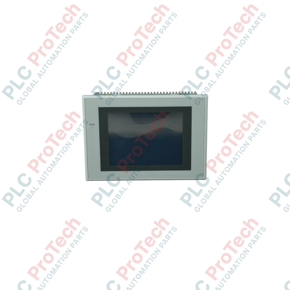
Engineered to deliver highly reliable human-machine interface (HMI) visualization within industrial automation architectures, the Omron NS5-SQ01B-V2 provides dynamic display and control capabilities in a compact footprint. This unit is optimized for seamless integration with Sysmac-compatible controllers, offering an efficient interface for monitoring machine telemetry and adjusting system parameters in real time. Operating on a standard 24 VDC input, the device minimizes energy overhead while maintaining high display clarity in demanding manufacturing environments.
Features
- Compact, highly responsive 5.7-inch STN color LCD touch screen interface.
- Low power consumption profile drawing a maximum of 15 W.
- Robust diagnostic capabilities with onboard system event logging.
- Dual RS-232C communication ports for simultaneous peripheral and PLC connectivity.
- Internal SRAM backup supported by a field-replaceable long-life lithium battery.
Applications
- Automotive assembly cell visualization and localized tool control.
- Packaging and labeling machine operators' interfaces.
- Water and wastewater municipal monitoring panels.
- Food and beverage processing line parameter management.
Technical Specifications
| Parameter |
Specification |
| Manufacturer |
Omron |
| Model Number |
NS5-SQ01B-V2 |
| Series |
NS Series HMI |
| Input Voltage |
24 VDC |
| Power Consumption |
15 W maximum |
| Display Size & Type |
5.7-inch STN Color LCD |
| Resolution |
320 x 240 pixels |
| Frame Color |
Black |
| Memory Backup Battery Life |
5 years typical (SRAM retention) |
| Ambient Operating Temperature |
0 to 50 degC |
| Net Weight |
1.0 kg |
| Shipping Weight (Calculated) |
1.8 kg |
Connections and Interfaces
| Port / Connection |
Functional Assignment |
| Serial Port A |
RS-232C interface for high-speed PLC or controller connection. |
| Serial Port B |
RS-232C interface for peripheral devices, temperature controllers, or bar code readers. |
| USB Slave Port |
Type-B port dedicated to CX-Designer programming upload and download. |
| Expansion Interface |
Supports optional controller link or video input expansion modules. |
Alternative Models & Compatibility
The NS5-SQ01B-V2 is the direct functional replacement for the older NS5-SQ01-V2 (which utilizes an ivory bezel) and can drop directly into existing 5.7-inch panel cutouts without physical modifications. For installations requiring direct Ethernet-based communication, the NS5-SQ11B-V2 represents the identical form-factor alternative featuring an integrated RJ45 network port instead of relying solely on serial links.
Application Pitfalls & Engineering Notes
When designing enclosures, ensure localized convective cooling keeps the surrounding air temperature within the 0 to 50 degC operating envelope. In environments subject to high levels of electromagnetic interference (EMI), ensure the display frame ground is securely connected to a dedicated low-impedance ground point to mitigate touch-matrix jitter or unexpected reset sequences.
Commissioning & Wiring Tips
When configuring communications via CX-Designer, ensure the baud rate settings of Serial Port A or B match the host PLC's hardware configuration. To preserve critical operational logs, recipe memories, and system clocks, track the HMI backup battery lifecycle; a low battery alarm indicates that the internal 3V lithium battery (CJ1W-BAT01) must be swapped while power is applied to the panel to avoid losing volatile SRAM data.
Installation Guidelines
CRITICAL WARNING:
Isolate and lock out all 24 VDC power sources prior to physical installation or terminal wiring. Verifying de-energization prevents electrical shocks and structural damage to internal communication transceivers.
1
Verify that the panel cutout dimensions exactly match the 5.7-inch enclosure specifications (150 mm x 121 mm) and check that the rubber sealing gasket is properly seated around the HMI bezel.
2
Insert the unit into the cutout and secure it from the rear using the provided mounting brackets, tightening them evenly to prevent display warping or ingress compromise.
3
Connect the functional earth (FE) wire to the dedicated grounding terminal using a 2 mm² or larger green ground lead.
4
Attach the 24 VDC power supply cables, ensuring proper polarity, then connect serial and programming cables prior to initial system power-up.