Description
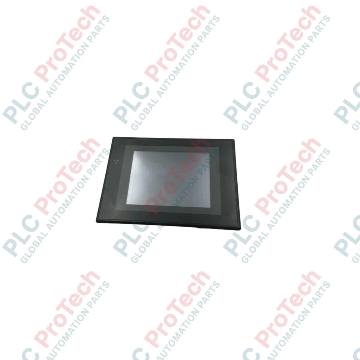
Facilitating advanced machine-to-operator visualization, the Omron NS5-SQ10B-EVV2 terminal is an industrial human-machine interface designed for real-time monitoring and control in automated setups. Engineered to integrate seamlessly with Sysmac automation platforms, this unit provides a highly legible, resistive analog touch display for machine adjustments, alarm tracking, and data log processing. It operates on a standard 24 VDC power input, making it a reliable diagnostic and interface point for industrial control panels.
Features
- High-contrast 5.7-inch TFT color LCD screen offering clear visibility under typical industrial lighting.
- Integrated dual RS-232C serial ports for direct connection to PLCs, temperature controllers, and specialized drives.
- Onboard Ethernet port supporting FINS/TCP communication for high-speed network diagnostics and data transfers.
- Long-life internal backup battery preserving system memory, clock data, and alarm histories during power cycles.
- Analog resistive touch technology allowing customized touch targets and precise screen inputs even when operators wear industrial gloves.
- Robust front panel design rated at IP65F for protection against dust, water spray, and oil mist.
Applications
- Automated packaging and material handling conveyor lines.
- Automotive subsystem and assembly line control visualization.
- Water treatment systems and local environmental processing panels.
- OEM machine integration and standalone product manufacturing machines.
Technical Specifications
| Parameter |
Value / Specification |
| Manufacturer |
Omron |
| Model Reference |
NS5-SQ10B-EVV2 |
| Display Type |
TFT Color LCD |
| Screen Size |
5.7 inches (diagonal) |
| Resolution |
320 x 240 pixels (QVGA) |
| Input Voltage |
24 VDC (acceptable range: 20.4 to 27.6 VDC) |
| Power Consumption |
15 W maximum |
| Battery Backup Life |
5 years typical (at 25 degC) |
| Ambient Operating Temperature |
0 to 50 degC |
| Operating Humidity |
35% to 85% RH (non-condensing) |
| Front Panel Protection |
IP65F oil-proof / dustproof (when panel-mounted correctly) |
| Unit Weight |
1.0 kg |
| Shipping Weight (Calculated) |
8.0 kg (including bulk packaging) |
Connections and Interfaces
| Port / Interface |
Functional Assignment / Purpose |
| Serial Port A |
RS-232C, D-Sub 9-pin female (Host Link or 1:N NT Link protocol) |
| Serial Port B |
RS-232C, D-Sub 9-pin female (Connection to host PLC, barcode reader, or temp controller) |
| Ethernet |
RJ-45 (10Base-T/100Base-TX) for remote programming, monitoring, and multi-PLC communication |
| USB Host |
Type A connector for local memory backup, logging, and project transfer via USB flash drives |
| USB Slave |
Type B connector dedicated to direct screen design uploads/downloads from CX-Designer |
Empirical Engineering Insights
Alternative Models & Compatibility
The "EVV2" designation indicates an integrated Ethernet physical layer and updated system runtime version over standard legacy NS5-SQ10B-V2 units. When upgrading older hardware configurations, ensure that you adjust the target hardware model inside Omron CX-Designer to match the exact "EVV2" profile to prevent compile-time addressing mismatches and compilation failures.
Application Pitfalls & Engineering Notes
To prevent premature display aging and CCFL/LED backlight burnout, configure the automatic Screen Saver function in your project properties to dim or power down the display backlight after 10 to 15 minutes of user inactivity. Also, avoid installing the terminal directly adjacent to heat-dissipating dynamic braking resistors or high-current AC contactors to maintain operational temperatures below the 50 degC ceiling.
Commissioning & Wiring Tips
For highly localized electromagnetic environments, ground the terminal's functional ground (FG) pin to a dedicated grounding point. Sharing an FG circuit with high-inductive loads like solenoids or drive motors introduces common-mode electrical noise, which can result in intermittent touchscreen ghost presses or unexpected communication link timeouts on the RS-232C ports.
Installation Guidelines
CRITICAL WARNING: Completely isolate and de-energize all primary and secondary power sources to the machine or control enclosure before starting mechanical installation or removing wiring terminals. Failure to verify zero-voltage state can cause severe electrical shock, circuit damage, or trans-receiver failure on connected PLC communications lines.
1
Ensure the control panel cutout dimensions conform exactly to the physical sizing parameters required for the 5.7-inch enclosure to prevent flexing of the HMI chassis.
2
Position the mounting gasket smoothly inside the front bezel perimeter to secure a true IP65F environmental seal against oil and water ingress.
3
Insert the hardware panel-mounting brackets into their corresponding slots and tighten them evenly to the specified torque rating, preventing touch panel warping.
4
Attach the terminal's 24 VDC power supply lines, keeping the DC run physically isolated from high-voltage AC cables inside the wire trunking.