Description
Designed for high-speed motion tracking within the Sysmac automation platform, the Omron NX-EC0122 provides high-speed incremental encoder input processing over the high-speed NX I/O Bus. It supports high-resolution PNP incremental encoders, offering real-time synchronization with machine controllers for applications demanding exact positioning. This module allows multi-mode signal processing, adapting to varying scan cycle demands to maintain system performance.
Features
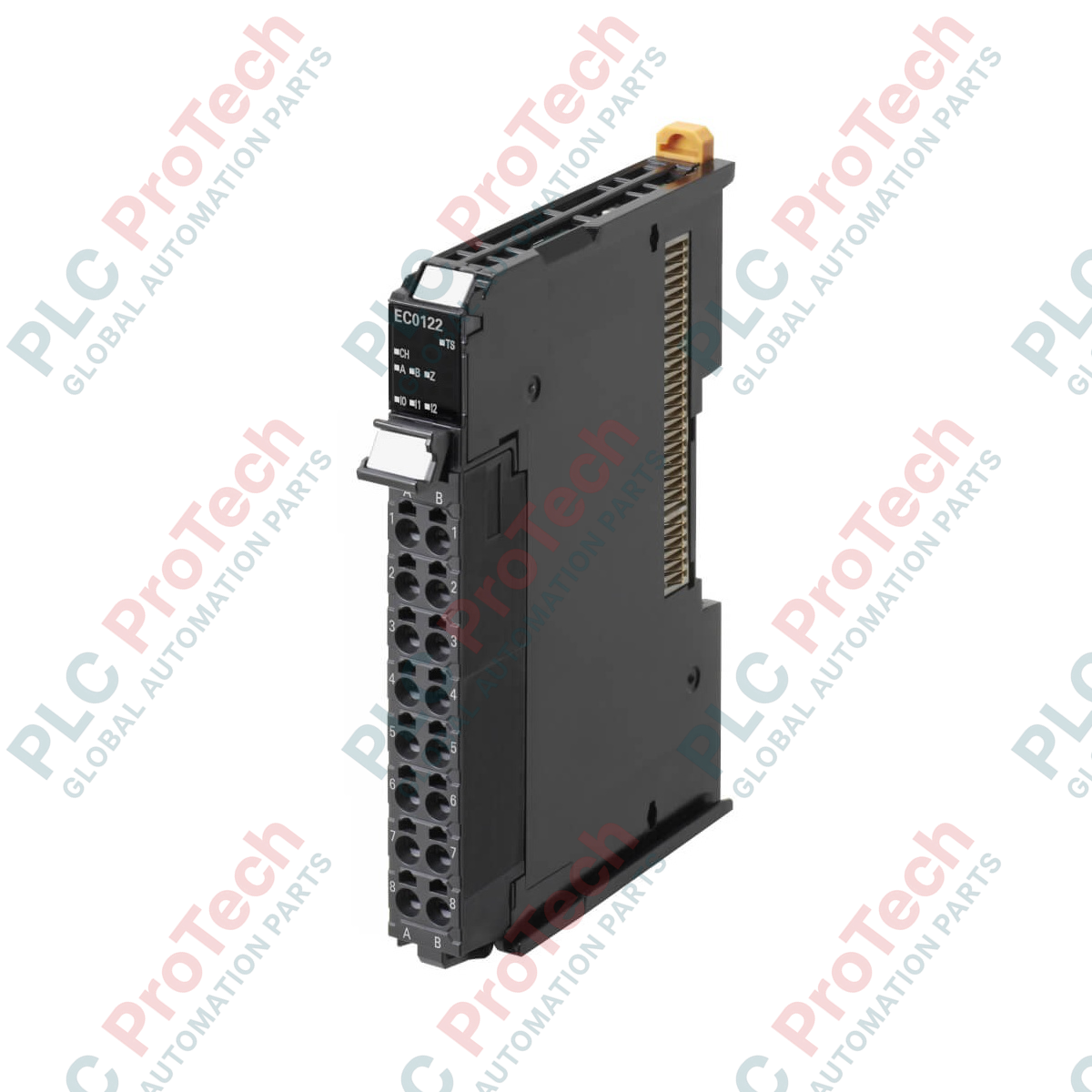
- Single-channel incremental encoder input supporting PNP interface types.
- High-speed response capability with a maximum input frequency of 500 kHz.
- Flexible processing architectures, featuring Free running, Synchronous, and Task period prioritized modes.
- Direct integration with the Sysmac Studio software platform for simplified configuration and diagnostics.
- Detachable, toolless push-in connection system to minimize wiring time and physical footprint.
- Four IOV and four IOG power supply terminals, allowing integrated encoder distribution.
Applications
- High-speed packaging and continuous rotary sealing lines.
- Synchronized conveyor belt material tracking and sorting.
- Web handling, unwinding, and tension control processes.
- Dynamic positioning systems coupled with servo and variable speed drives.
Technical Specifications
| Parameter |
Specification |
| Manufacturer |
Omron |
| Model Number |
NX-EC0122 |
| Module Type |
Encoder Input (Incremental) |
| I/O System Connection |
NX I/O Bus |
| Digital Input Type |
Incremental encoder, PNP |
| Number of Channels |
1 Channel |
| Max. Encoder Input Frequency |
500 kHz |
| Signal Processing Modes |
Free running, Synchronous, Task period prioritized |
| I/O Connection Type |
Push-in Terminal Block (12 terminals) |
| Detachable Terminal Block |
Yes |
| Power Terminals |
4x IOV (V+), 4x IOG (V-) |
| IP Rating |
IP20 |
| Dimensions (H x W x D) |
104.5 mm x 12 mm x 80.1 mm |
| Net Weight |
70 g |
| Shipping Weight (Calculated) |
1.0 kg (packaged) |
Connections and Interfaces
| Terminal Label |
Function Assignment |
| A / B / Z |
Incremental Encoder Phases A, B, and Z inputs (PNP level) |
| IOV |
Power supply positive terminals for connected encoders (4 terminals total) |
| IOG |
Power supply common/ground terminals for connected encoders (4 terminals total) |
| NC |
No connection / Reserved |
Alternative Models & Compatibility
The NX-EC0122 is designed for PNP interface configurations. If your hardware architecture requires NPN open-collector or differential line driver signal handling, you must source the NX-EC0112 (NPN) or NX-EC0142 (Line Driver) respectively. It integrates directly with NX-series bus couplers (EtherCAT or EtherNet/IP) and Sysmac NX102 or NX1P2 series controllers.
Application Pitfalls & Engineering Notes
Verify the aggregate current load drawn from the IOV/IOG distribution terminals. While the 4 terminals simplify wiring, they draw from the internal NX-bus power supply; if the encoder's power consumption exceeds the NX bus limits, an external auxiliary power supply must be integrated to prevent bus voltage dropouts. At high pulse frequencies close to the 500 kHz threshold, signal distortion can occur if routing cabling over distances greater than 10 meters without high-quality low-capacitance shielded wire.
Commissioning & Wiring Tips
Ensure encoder cables are separated from high-voltage AC power lines by at least 100 mm to suppress electromagnetic interference. Terminate the cable shield only at the designated industrial grounding bar or communication coupler clamp. To prevent damage to the push-in spring clamps, use only recommended wire ferrules with solid cores, keeping the insulation stripping length precise to avoid short circuits between adjacent active terminals.
Installation Guidelines
CRITICAL WARNING: Ensure all power supplies to the NX rack assembly, auxiliary distribution networks, and field sensors are physically isolated and locked out before attempting installation, wiring, or maintenance of this unit.
1
Align the guide rail on the side of the NX-EC0122 with the adjacent NX unit on the DIN rail.
2
Slide the module down until it firmly clicks onto the 35mm DIN rail and is locked with its neighbor unit.
3
Wire the encoder connections (Phases A/B/Z and IOV/IOG supply paths) using ferruled control lines inserted into the push-in block.
4
Power up the system and verify standard operational LED status via the primary industrial communication coupler.