Description
Integrating high-resolution thermal tracking directly into Sysmac automation systems, the Omron NX-TS2204 provides dual-channel resistance temperature detector monitoring for high-precision industrial processes. Operating on the high-speed NX bus architecture, this module supports three-wire Pt100 and Pt1000 sensors with a rapid conversion speed of 60 ms per unit and an exceptional measurement resolution of 0.001 degC. Designed to maintain signal integrity in electrically noisy environments, it incorporates channel-to-channel and channel-to-bus galvanic isolation via built-in power transformers and digital signal isolators.
Features
- Dual-point input configuration supporting standard three-wire Pt100 and Pt1000 RTD sensors.
- Ultra-fine processing resolution of 0.001 degC maximum for sensitive process control applications.
- Free-Run refreshing method ensures asynchronous, continuous temperature updates independent of task cycles.
- High-density 12 mm wide form factor saves valuable panel space on standard DIN rail mounting.
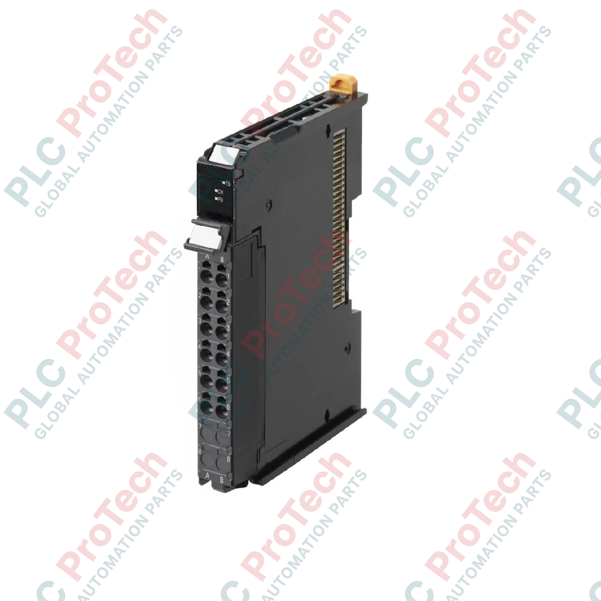
- Screwless clamping terminal block featuring 16 points for fast, secure, gas-tight field wiring.
- Advanced isolation barriers between input channels and internal NX bus circuitry to prevent ground loop interference.
Applications
- Multi-zone thermal control in plastic extrusion, injection molding, and thermoforming equipment.
- Environmental chamber monitoring and high-accuracy industrial drying processes.
- Pasteurization and cooking systems within food, beverage, and packaging lines.
- Cleanroom ambient environmental logging and semiconductor fabrication HVAC monitoring.
Technical Specifications
| Specification Parameter |
Technical Value |
| Manufacturer |
Omron |
| Model Number |
NX-TS2204 |
| Product Type |
Temperature Input Unit (Resistance Thermometer) |
| Number of Inputs |
2 points |
| Supported Temperature Sensors |
Pt100 (three-wire), Pt1000 (three-wire) |
| Conversion Time |
60 ms per Unit |
| Resolution |
0.001 degC max. |
| I/O Refreshing Method |
Free-Run refreshing |
| External Connection Terminals |
Screwless clamping terminal block (16 terminals) |
| Input Conversion Range |
+/-20 degC of the input range |
| Input Detection Current |
Approx. 0.25 mA |
| Conductor Resistance Effect |
0.06 degC/Ohm max. (up to 20 Ohms max.) |
| Warm-up Period Requirement |
30 minutes |
| Isolation Method |
Power: Transformer; Signal: Digital Isolator (Input-to-bus & Channel-to-channel) |
| Insulation Resistance |
20 MOhms min. between isolated circuits (at 100 VDC) |
| Dielectric Strength |
510 VAC between isolated circuits for 1 minute (leakage current 5 mA max) |
| NX Unit Power Consumption |
0.90 W max. (on CPU Unit); 0.75 W max. (on Communications Coupler) |
| I/O Power Supply Method |
No external I/O power supply required |
| Dimensions (W x H x D) |
12 x 100 x 71 mm |
| Unit Weight |
0.07 kg |
| Shipping Weight |
1.00 kg |
Empirical Engineering Insights
Alternative Models & Compatibility
The NX-TS2204 is a highly specialized RTD input unit. If your system relies on thermocouple inputs rather than resistance thermometers, the NX-TS2101 or NX-TS2102 should be selected instead. Ensure your Sysmac Studio software is updated to match the firmware revision of your NX-series CPU or communications coupler to guarantee full parameter configuration capabilities.
Application Pitfalls & Engineering Notes
A warm-up period of 30 minutes is strictly required after turning on the power supply to ensure the internal components reach stable thermal equilibrium. Accurate temperature monitoring depends on balanced conductor resistances; an unbalance between the three wires of the RTD sensor will lead directly to temperature measurement drift, adding a maximum of 0.06 degC per Ohm of resistance discrepancy.
Commissioning & Wiring Tips
Always route the sensor cables through dedicated low-voltage instrument trays separate from high-power AC lines. We recommend grounding the shielded sheath of your RTD cables at a single point near the module to avoid circulating currents and shield noise coupling. Double check that the terminal pins are inserted with a proper crimped ferrule for optimal long-term contact in high-vibration panels.
Installation Guidelines
CRITICAL WARNING: ELECTRICAL SHOCK AND SYSTEM DAMAGE
Isolate all electrical power sources supplying the PLC rack and the input devices before inserting, removing, or wiring any NX module. Failure to de-energize the entire control system can lead to unexpected machine movement, electrical shock, or permanent damage to the NX backplane communication circuit.
1
Mount the module onto the DIN rail by aligning the upper hook of the unit with the rail and pressing down until the lock clicks securely into position.
2
Wire the three-wire Pt100/Pt1000 sensors into the screwless clamping terminal block by inserting a flat-blade tool into the release hole, inserting the wire, and removing the tool to lock.
3
Power up the system and monitor the "TS" indicator on the front panel: a solid green light indicates normal operating status, while red indicators flash to signal diagnostic errors such as wire breaks or sensor short circuits.