Description
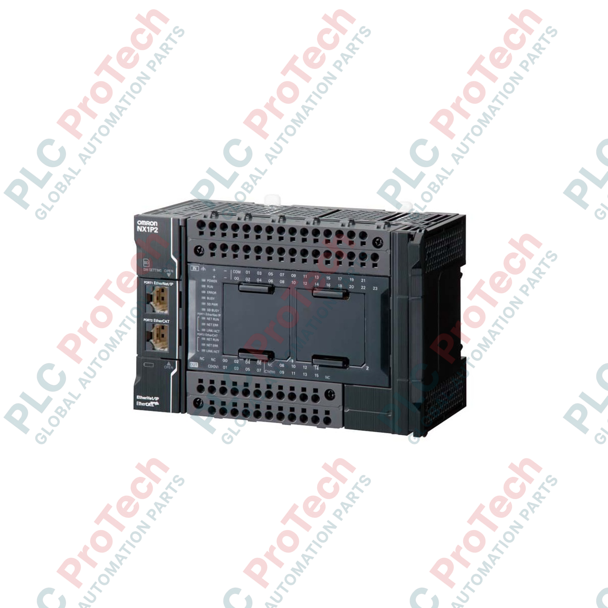
Designed for integrated control of small-scale motion and sequence applications, the Omron NX1P2-1140DT1 execution platform delivers advanced processing within the Sysmac automation architecture. By incorporating built-in I/O, EtherCAT network control, and EtherNet/IP communications in a compact housing, this controller serves as a highly deterministic automation hub. Engineered for real-time responsiveness, it executes its primary task cycle in 2 ms, utilizing 1.5 MB of program memory and 2 MB of variables memory to execute sophisticated control algorithms without lag. The integrated I/O configuration features 40 terminal points configured with PNP sourcing output logic, facilitating direct interface with modern industrial field devices.
Features
-
Synchronous Motion Control: Supports real-time electronic gearing, camming, and multi-axis interpolation.
-
Built-in I/O Architecture: Includes 40 solid-state points (24 inputs, 16 sourcing/PNP outputs) directly on the module.
-
Dual Network Capability: Built-in ports for EtherCAT (Master) and EtherNet/IP allow simultaneous high-speed motion synchronization and enterprise-level factory integration.
-
Sysmac Studio Integration: Configured and programmed through a single, unified software platform.
-
Expandability: Easily interfaces with NX-series I/O modules and option boards for serial and analog communication expansion.
Applications
- High-speed packaging and labeling machinery.
- Multi-axis pick-and-place gantry systems.
- Precision filling, dosing, and bottling systems.
- In-feed/out-feed material handling and conveyor tracking.
Technical Specifications
| Manufacturer |
Omron |
| Model Number |
NX1P2-1140DT1 |
| Control Series |
Sysmac NX1P |
| Primary Task Cycle Time |
2 ms |
| Program Memory |
1.5 MB |
| Variables Memory |
2 MB |
| Communication Interfaces |
EtherCAT Master, EtherNet/IP, Ethernet TCP/IP |
| Built-in I/O Configuration |
40 Points: 24 Inputs, 16 Outputs (Transistor, PNP Sourcing) |
| Supply Voltage Range |
20.4 to 28.8 VDC |
| Net Weight |
0.66 kg |
| Shipping Weight (Calculated) |
3.00 kg |
| Dimensions (L x W x H) |
7.1 cm x 14.8 cm x 10.0 cm |
| Country of Origin |
Japan |
Connections and Interfaces
| Port / Terminal Group |
Functional Assignment |
| EtherCAT Port |
RJ45 connection to servo drives, remote I/O couplers, and vision sensors. |
| EtherNet/IP Port |
RJ45 connection for HMI, SCADA, database connectivity, and configuration. |
| Power Supply Terminal |
Direct connection for 24 VDC main controller system power. |
| Input Terminals |
24 points, compatible with standard 24 VDC sinking or sourcing sensors. |
| Output Terminals |
16 points, PNP sourcing transistor configuration requiring external common. |
Alternative Models & Compatibility
The "DT1" suffix indicates that this controller utilizes PNP sourcing transistor outputs. For applications requiring NPN sinking outputs, you must select the alternate "DT" model. Upgrading from older CP-series controllers requires a full migration in Sysmac Studio. Ensure your IDE is updated to version 1.17 or higher to guarantee seamless device catalog identification and parameter programming for this hardware revision.
Application Pitfalls & Engineering Notes
To maintain high operational reliability, observe thermal clearance requirements inside the electrical cabinet. Ensure at least 30 mm of air gap above and below the module housing when operating near the upper ambient temperature range. Do not route high-voltage AC cables in parallel with the low-voltage DC lines supplying the built-in I/O to avoid electromagnetic interference and false transitions on the high-speed input interrupts.
Commissioning & Wiring Tips
Prior to commissioning the unit, confirm that the external I/O power supply voltage is regulated to standard VDC parameters and matches the common reference of the output terminals. Always utilize double-shielded Cat5e STP cabling for the EtherCAT ring to guarantee signal integrity under high-frequency electromagnetic noise. If utilizing the built-in encoder inputs, route differential signal lines through separate conduits directly to the terminals.
Installation Guidelines
CRITICAL WARNING: Verify that all AC and DC source power circuits are locked out and completely de-energized before mounting, wiring, or inserting expansion boards. Failure to fully isolate high voltage potentials can result in permanent semiconductor destruction within the CPU processing board.
1
Mount the module vertically onto a clean, standardized 35mm DIN rail, ensuring the locking tabs lock securely into place.
2
Connect the main protective earth terminal to the control panel central ground bar using low-impedance conductor lines.
3
Secure the 24 VDC power supply wiring directly to the designated power terminals, verifying the polarity of the positive and common conductors.
4
Insert the pre-configured EtherCAT and EtherNet/IP communication cables into their respective RJ45 interfaces, checking for a positive tactile click.