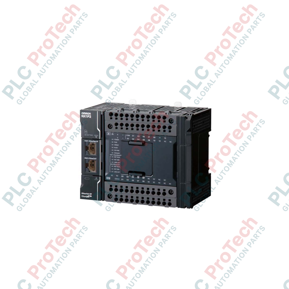
Description
Executing complex motion profiles and machine control tasks with deterministic precision, the Omron NX1P2-9024DT functions as a compact, self-contained Sysmac automation controller. This unit combines a powerful processor, built-in digital I/O, and dedicated industrial communication ports into a single form factor to manage up to 8 EtherCAT nodes. Designed for modern tag-based architectures, it utilizes the unified Sysmac Studio software platform to integrate logic, motion, and networking, reducing engineering overhead in high-throughput applications.
Key Technical Features
-
Integrated Execution Engine: Fast 2.0 ms primary task cycle time for synchronized motion and logic processing.
-
Memory Architecture: Generous 1.5 MB program capacity paired with 2 MB of variables memory for complex data handling and recipe storage.
-
Dual Ethernet Networking: Features dedicated ports for EtherCAT master synchronization and standard EtherNet/IP or TCP/IP factory networking.
-
Onboard Digital I/O: Outfitted with 24 built-in execution points, consisting of 14 inputs and 10 sinking NPN transistor outputs.
-
Local Expansion: Support for up to 8 local NX-series digital, analog, or temperature control expansion units on the same DIN rail.
Industrial Applications
-
High-Speed Packaging: Drives form-fill-seal machines, multi-lane labeling systems, and indexing conveyors.
-
Precision Assembly: Coordinates pick-and-place gantry robots and rotary dial assembly tables using coordinated motion axes.
-
Material Handling: Controls sorting conveyors, automated transfer cars, and lifter stations with real-time fieldbus feedback.
-
In-Line Inspection Systems: Triggers high-speed vision cameras and processes multi-sensor quality check arrays.
Technical Specifications
| Parameter |
Specification |
| Manufacturer |
Omron Industrial Automation |
| Model Reference |
NX1P2-9024DT |
| Product Line |
Sysmac NX1P Series |
| Supply Voltage |
24 VDC (Acceptable range: 20.4 to 28.8 VDC) |
| Power Consumption |
10 Watts maximum (CPU unit only) |
| Program Memory |
1.5 MB |
| Variables Memory |
2 MB |
| Built-In Inputs |
14 points (24 VDC, sinking/sourcing) |
| Built-In Outputs |
10 points (Transistor NPN, sinking) |
| Integrated Interfaces |
1x EtherCAT Master, 1x EtherNet/IP (TCP/IP) |
| EtherCAT Node Capacity |
Up to 16 nodes (including up to 8 synchronized axes) |
| Primary Task Cycle |
2.0 ms minimum |
| Net Weight |
0.59 kg |
| Shipping Weight (Calculated) |
3.00 kg (including protective packaging) |
| Dimensions (W x H x D) |
124 mm x 100 mm x 71 mm |
Empirical Engineering Insights
Alternative Models & Compatibility
When migrating legacy systems, recognize that the Sysmac NX1P2 does not support CX-Programmer code directly. Programs from CP-series or CJ-series controllers must be manually migrated to Sysmac Studio (version 1.13 or higher). If your field topology requires sourcing PNP outputs rather than sinking NPN outputs, you must specify the companion model NX1P2-9024DT1 instead of this sinking unit.
Application Pitfalls & Engineering Notes
Pay strict attention to the NX Unit Power Supply Capacity. The internal bus power supply capacity of this CPU is limited to 1.6 Amps. If you mount power-hungry analog or high-speed counter expansion units directly to the local bus, calculate the cumulative consumption. Overdrawing the bus power will result in a "Unit Bus Power Overcurrent" fault and system halt. If the current budget is exceeded, an auxiliary NX-PD1000 power supply unit must be inserted.
Commissioning & Wiring Tips
The integrated Push-In Plus terminal blocks require a crimped ferrule length of exactly 8 mm or 10 mm. Avoid using bare stranded copper wire directly without ferrules to prevent intermittent connections under vibration. For noise-critical communications over the primary EtherCAT port, utilize double-shielded STP Cat5e (or higher) cables with grounded metal-shell RJ45 connectors to prevent industrial electromagnetic interference from corrupting the real-time network packets.
Installation Guidelines
CRITICAL WARNING:
Before installing, removing, or wiring any module, completely de-energize the main panel. Failure to disconnect the 24 VDC input power source prior to terminal work can cause permanent damage to the CPU logic circuits and corrupt the internal flash memory partition.
1
Mount the CPU module onto standard 35 mm symmetric DIN rail. Ensure the sliding lock mechanism on the bottom of the housing clicks securely into place.
2
Connect a dedicated Functional Ground wire (minimum 2.0 mm2 cross-section) directly from the CPU ground terminal block to the main panel's copper grounding busbar.
3
Plug in the EtherCAT network cable to the built-in communication port, ensuring the cable routing remains separated from high-voltage AC motor drives.
4
Verify that all downstream NX local expansion modules are firmly latched to each other and that the bus end plate is securely fixed to the rightmost unit.