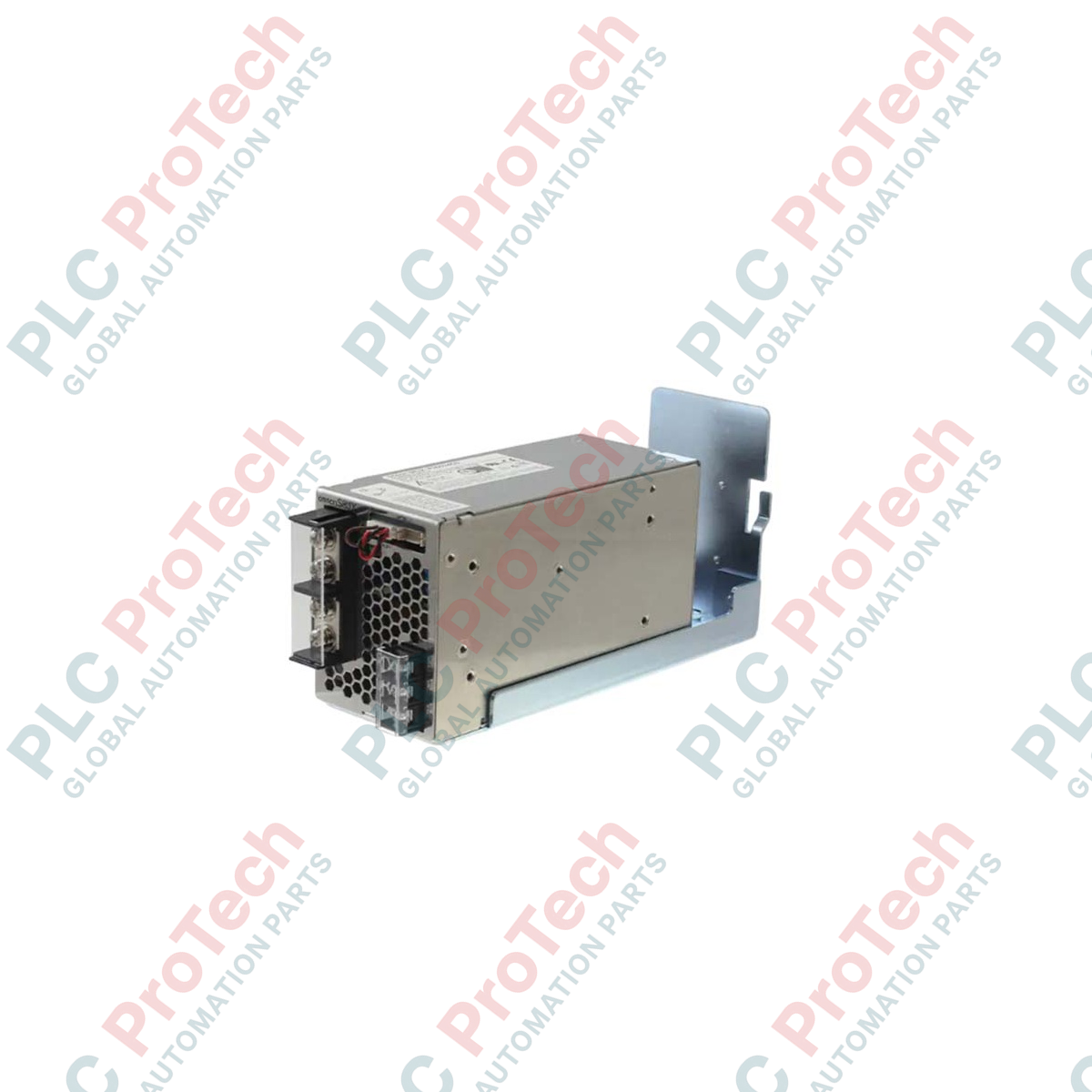
Description
Designed for stable and reliable DC distribution within industrial control systems, the Omron S8JX-P30024CD delivers regulated 24 VDC power to sensitive automated components. Featuring an integrated harmonic current suppression circuit conforming to IEC 61000-3-2, this 300W power supply mitigates noise feedback into the primary line, ensuring high performance in dense electrical cabinets. The DIN rail mounting design (indicated by the CD suffix) facilitates rapid installation, while the rugged metal enclosure and built-in cooling fan provide thermal stability under continuous heavy-duty operations.
Key Features
-
Harmonic Suppression: Built-in Power Factor Correction (PFC) circuitry reduces electrical noise and complies with IEC 61000-3-2 standards.
-
Overcurrent Protection: Automatic recovery system limits output current during overloads to prevent damage to downstream field devices.
-
Overvoltage Protection: Shuts down the output when internal voltages exceed safe operating parameters, requiring manual power cycle to reset.
-
Thermal Dissipation: Integrated cooling fan maintains optimal internal operating temperatures under full load conditions.
-
DIN Rail Integration: Factory-fitted bracket ensures robust mounting on standard 35mm top-hat rails.
Typical Industrial Applications
- PLC systems and distributed I/O rack power networks.
- Industrial sensor excitation and transmitter loops.
- 24 VDC control circuit relays and contactor coils.
- Machine tool control panels and material handling systems.
Technical Specifications
| Parameter |
Specification Values |
| Manufacturer |
Omron |
| Model Code |
S8JX-P30024CD |
| Input Voltage Range |
85 to 264 VAC (Single Phase, 47 to 63 Hz) or 120 to 370 VDC |
| Output Voltage |
24 VDC |
| Output Current Range |
14.0 A |
| Power Rating |
300 W |
| Efficiency (Typical) |
82% minimum at full load |
| Voltage Adjustment Range |
-10% to +15% (via front-panel potentiometer) |
| Mounting Style |
35mm DIN Rail Mount (Factory-installed metal bracket) |
| Cooling Method |
Forced-air cooling (built-in fan) |
| Operating Temperature |
-20 to +60 degC (Refer to derating curves for ambient exceeding 40 degC) |
| Product Weight |
0.95 kg (Approximate net weight) |
| Physical Dimensions |
249 mm x 77.6 mm x 123 mm |
| Shipping Weight (Calculated) |
1.50 kg |
Connections and Terminal Assignments
| Terminal Designation |
Function Description |
| L |
AC Line Input Terminal (Fuses internally on Line phase) |
| N |
AC Neutral Input Terminal |
| PE / Frame Ground |
Safety Earth Ground connection (Must be bonded to main panel ground) |
| +V (Multiple Terminals) |
Positive DC Output Terminals (24 VDC) |
| -V (Multiple Terminals) |
Negative DC Output Terminals (0 VDC Return) |
Empirical Engineering Insights
Alternative Models & Compatibility
The S8JX-P series was engineered as an updated alternative to standard S8JX-G models, specifically introducing harmonic current suppression to comply with broader international power grids. If replacing an older S8JX-G or transitioning to newer product lines, be aware that the S8VK-G and S8VK-WA series represent the modern replacement footprints. When switching to S8VK equivalents, verify the physical footprint and terminal layouts, as some S8VK models have a narrower width but deeper profile than the S8JX-P.
Application Pitfalls & Engineering Notes
The S8JX-P30024CD relies on active, forced-air cooling via an integrated fan. Mounting this unit in orientations other than standard vertical DIN rail layout drastically limits heat dissipation. For standard operation, maintain a clearance of at least 20mm on both sides and 50mm above and below the device. Failure to keep these spaces free will trigger premature thermal derating or cause automatic overtemperature shutdown under high-load profiles.
Commissioning & Wiring Tips
When connecting a 14A continuous load, copper field-wiring with a minimum gauge of 14 AWG (2.5 mm²) is highly recommended to minimize localized heating and voltage drop at the terminals. Use ring or spade terminals properly sized for M4 terminal screws. Torque all input and output terminal screws strictly to 1.2 N-m to prevent loose, high-resistance connections under heavy vibration cycles.
Installation Guidelines
CRITICAL WARNING: Hazardous voltages are present on the primary terminals of this equipment. Ensure all upstream AC feed breakers are fully de-energized and locked out/tagged out prior to starting installation or performing terminal maintenance. Allow at least 5 minutes post-power-down for internal capacitors to discharge fully before touching any internal or external connections.
1
Clip the top hook of the power supply's integrated DIN-rail mount onto the upper edge of the standard 35mm rail.
2
Press the lower portion of the enclosure firmly toward the rail until the spring-loaded DIN rail latch snaps securely into place. Verify mechanical lock by trying to tilt the unit.
3
Terminate the safety ground connection to the PE terminal block using a dedicated earth wire before making any primary power or secondary DC connections.
4
Connect the primary Line (L) and Neutral (N) lines, then the 24 VDC positive (+V) and negative (-V) DC lines to their respective terminal outputs. Ensure appropriate wire gauge and check torque settings.