Description
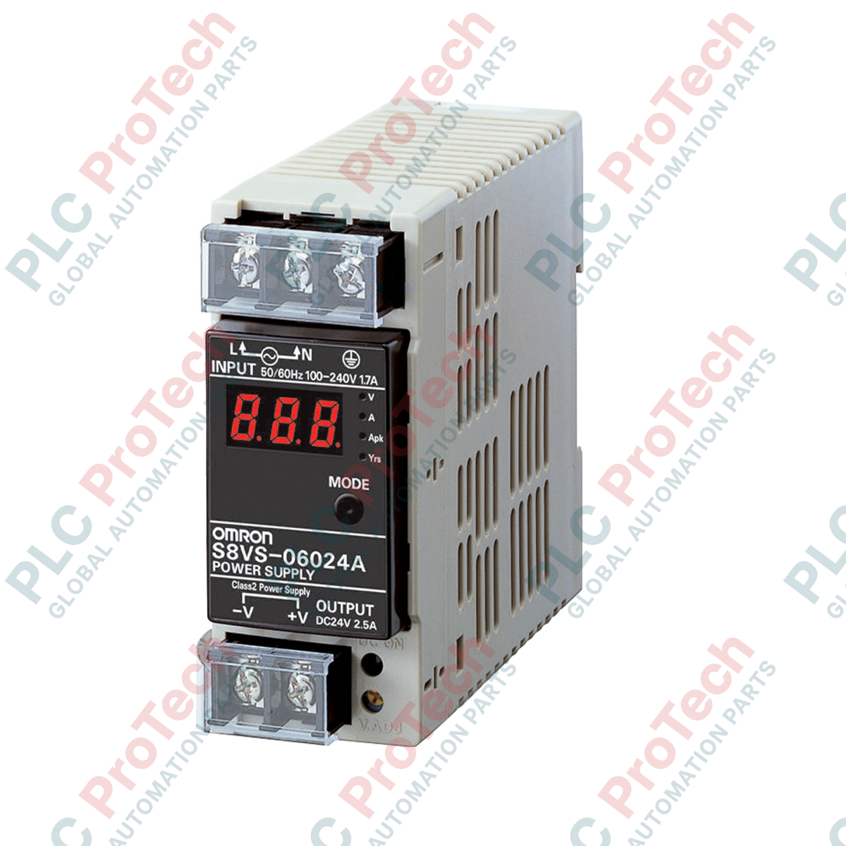
Providing stabilized 24 VDC power to sensitive control circuits, the Omron S8VS-06024A is a DIN-rail mount switch-mode power supply featuring an integrated maintenance forecast monitor. This industrial-grade power module delivers a continuous 60 W output (2.5 A at 24 VDC) and is equipped with a 3-digit, 7-segment LED display that proactively tracks the remaining service life of the internal electrolytic capacitors. By calculating operating temperature and runtime, the unit provides maintenance engineers with predictive diagnostic data to prevent unscheduled machine downtime.
Key Features
-
Predictive Maintenance Display: Built-in LED screen alternates between output voltage, output current, peak hold current, and remaining lifetime (years).
-
Universal Input Range: Accepts wide-ranging AC input (100 to 240 VAC) and DC input (80 to 370 VDC) for global deployment compatibility.
-
Convection Cooling: Designed for natural air-cooling, eliminating mechanical fan failures and increasing overall system reliability.
-
Robust Protection Circuitry: Includes automatic-recovery overload protection and overvoltage shutdown mechanisms.
-
Compact Form Factor: Slender profile optimizes valuable cabinet space on standard 35mm symmetrical DIN rails.
Typical Industrial Applications
- PLC rack and I/O module system power
- HMI and industrial PC cabinet power supplies
- Factory automation control panels requiring high-uptime monitoring
- Critical process instrumentation and telemetry fields
Technical Specifications
| Manufacturer |
Omron Industrial Automation |
| Model Number |
S8VS-06024A |
| Power Rating |
60 W |
| Rated Input Voltage |
100 to 240 VAC (Permissible: 85 to 264 VAC, 50/60 Hz) |
| DC Input Range |
80 to 370 VDC |
| Output Voltage |
24 VDC |
| Rated Output Current |
2.5 A |
| Cooling Method |
Natural air-cooling |
| Terminal Style |
M3.5 Screw Terminals |
| Mounting Type |
35mm DIN Rail |
| Product Dimensions |
40 mm (W) x 95 mm (H) x 108.3 mm (D) |
| Shipping Weight (Calculated) |
0.45 kg |
Terminal Connections
| Terminal Designation |
Function Description |
| L |
Input Terminal (Line / Phase) |
| N |
Input Terminal (Neutral) |
| PE (Ground Symbol) |
Protective Earth Ground Terminal |
| +V |
Positive DC Output Terminal |
| -V |
Negative DC Output Terminal |
| Mnt (Transistor Output) |
Maintenance Forecast Alarm Output (Photo-coupler) |
Empirical Engineering Insights
Alternative Models & Compatibility
The "A" suffix distinguishes this model from the standard, non-display S8VS-06024 variant. If integrating this into an older cabinet design, the physical dimensions and terminal pinouts are identical, permitting direct drop-in replacement. However, ensure that any external alarm PLC input channels are correctly wired to utilize the built-in collector output (Mnt terminal) for remote diagnostics.
Application Pitfalls & Engineering Notes
To ensure the accuracy of the maintenance lifetime calculation, avoid mounting the power supply in physical contact with high-heat generating elements such as braking resistors or motor drives. For optimal convective airflow, maintain a minimum clearance of 15 mm on the left and right sides and 75 mm above and below the chassis.
Commissioning & Wiring Tips
When wiring the AC input, use stranded copper wire with a rated thermal capacity of at least 75 degC. Ensure screw terminals are torqued precisely to 0.5 to 0.6 N-m to prevent local resistance overheating. If using a DC input source, correct polarity must be maintained: connect the positive leg to the "L" terminal and the negative leg to the "N" terminal.
Installation Guidelines
CRITICAL WARNING: Prior to attempting installation, wiring, or maintenance, isolate all primary AC or DC power feeds feeding the cabinet. Verify the absence of voltage on all terminals using a calibrated testing meter. Failure to de-energize can result in lethal electrical shock or equipment destruction.
1
Snap the rear bracket of the S8VS-06024A onto a standard symmetrical 35mm DIN rail, ensuring the top hook catches first before pressing the bottom lock into place.
2
Connect a solid protective earth ground wire to the PE terminal to guarantee electromagnetic compatibility and chassis safety.
3
Terminate input power conductors into the L and N screw terminals, verifying polarity if deploying with DC input.
4
Wire the +V and -V output load lines to the target circuit components, and configure the Mnt signal line to the safety PLC input if remote monitoring is required.