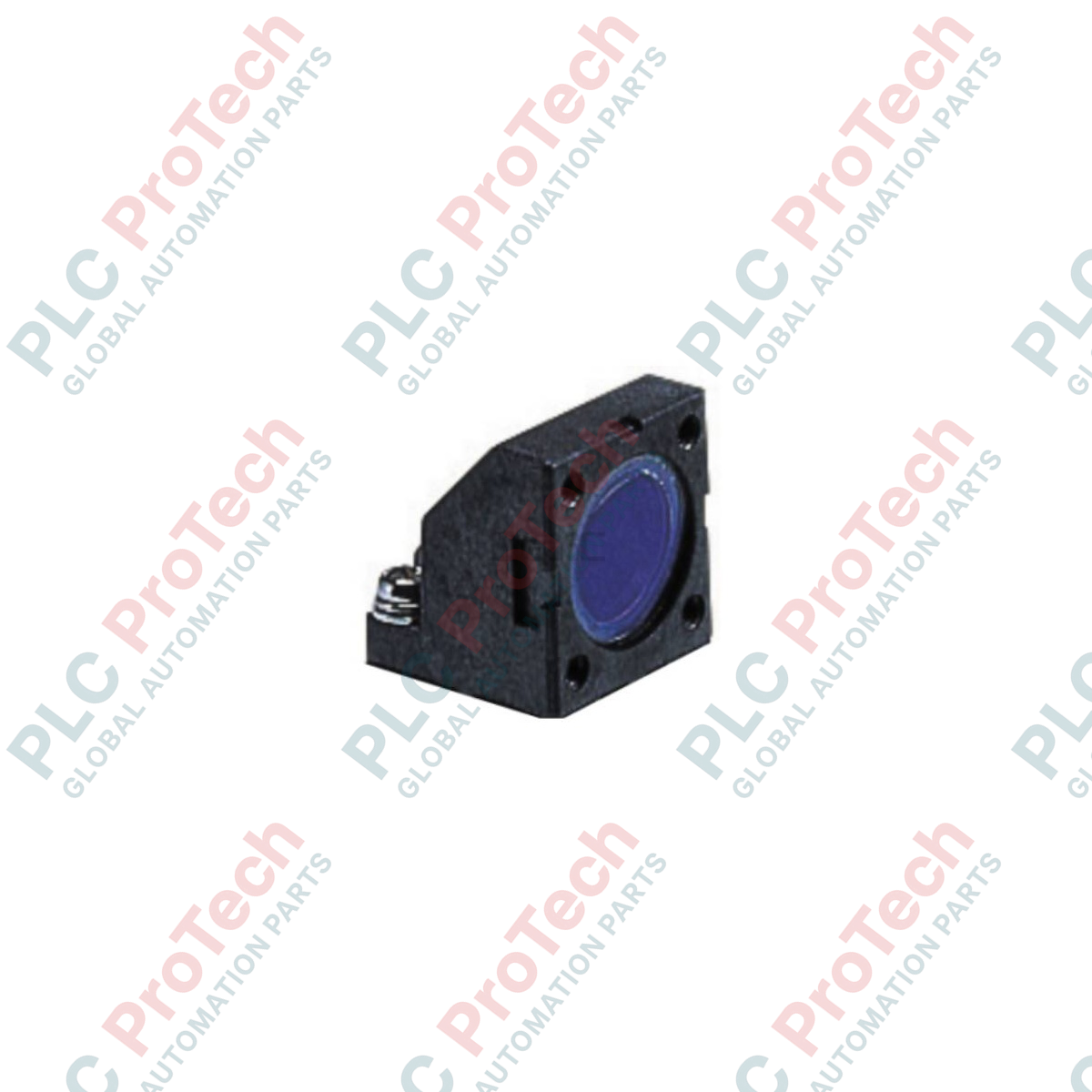
Description
Directing laser measurement beams into confined mechanical profiles is achieved using the Omron ZX-XF12, a high-precision optical side-view attachment designed specifically for the ZX-LD series of laser displacement sensor heads. This optical redirection accessory alters the laser measurement axis by exactly 90 degrees, allowing engineers to deploy advanced displacement tracking in tight gaps, compact machine interiors, and perpendicular alignment setups where standard linear mounting is physically impossible. Constructed with a rigid aluminum frame and highly reflective optical mirrors, the device maintains maximum beam integrity and minimal signal attenuation for consistent, high-accuracy measurement feedback.
Features
-
90-Degree Beam Redirection: Enables perpendicular displacement sensing in narrow channels and restricted footprints.
-
High-Reflectivity Optic: Engineered to minimize optical power loss and prevent distortion of the laser spot profile.
-
Rigid Structural Mount: Prevents micro-deflections and optical drift caused by high-frequency industrial machine vibrations.
-
Seamless Integration: Form-matched mechanical alignment with the Omron ZX-LD sensor head series without requiring custom brackets.
Applications
- Semiconductor wafer handling and processing gap measurement inside narrow processing chambers.
- In-line automotive assembly thickness verification within deep mechanical recesses.
- Electronic component height inspection on densely populated PCB transport tracks.
Technical Specifications Table
| Parameter |
Specification |
| Manufacturer |
Omron |
| Model |
ZX-XF12 |
| Accessory Type |
Side-view Attachment |
| Optical Redirection Angle |
90 degrees |
| Compatible Sensor Heads |
Omron ZX-LD Series (e.g., ZX-LD40, ZX-LD100) |
| Material Composition |
Anodized Aluminum and Precision Glass Mirror |
| Product Weight |
0.05 kg |
| Shipping Weight (Calculated) |
0.15 kg |
| Package Dimensions (Calculated) |
80 mm x 60 mm x 45 mm |
Empirical Engineering Insights
Alternative Models & Compatibility
The ZX-XF12 is designed explicitly for the ZX-LD coaxial and diffuse laser sensor heads. Note that adding this optical accessory alters the nominal measuring center distance and the overall measuring range due to the extended internal optical path. Always reference the sensor head's adjusted calibration curve in the Omron manual when configuring scale factors and zero-point offsets in the ZX-series amplifier controller.
Application Pitfalls & Engineering Notes
Because this unit relies on an external reflecting mirror, optical path contamination is a critical failure mode. In environments with heavy oil mist, airborne dust, or condensation, the mirror will accumulate particles, causing light dispersion and resulting in "DARK" or "NEAR" error codes on the controller. In these conditions, design an air-purge collar or an IP-rated protective enclosure around the measurement point.
Commissioning & Calibration Tips
When mounting the ZX-XF12 to the ZX-LD head, ensure the securing screws are torqued evenly according to Omron specifications. Uneven mechanical stress can warp the attachment housing, throwing the mirror out of parallel alignment and shifting the reflected measurement beam off-center. After physical installation, perform a complete zero-point calibration and test the system linearity using a master gauge.
Installation Guidelines
CRITICAL WARNING: LASER RADIATION SAFETY
Power down the laser sensor controller or physically de-energize the sensor head before installing or adjusting the side-view attachment. Direct or specular reflection of Class 2 or Class 3R laser beams into the eyes can cause permanent retinal damage. Never look directly into the deflection mirror during active operation.
1
Clean the emitter and receiver optics of the ZX-LD laser head and the mirror face of the ZX-XF12 using oil-free industrial lens wipes and isopropyl alcohol.
2
Align the mating guide pins of the ZX-XF12 with the corresponding alignment slots on the front face of the sensor head.
3
Insert and gradually tighten the mounting screws in an alternating pattern to ensure flush, parallel mating. Do not overtighten.
4
Power up the controller, verify the target surface is within the newly offset measurement range, and execute the controller's zero-point calibration routine.