Description
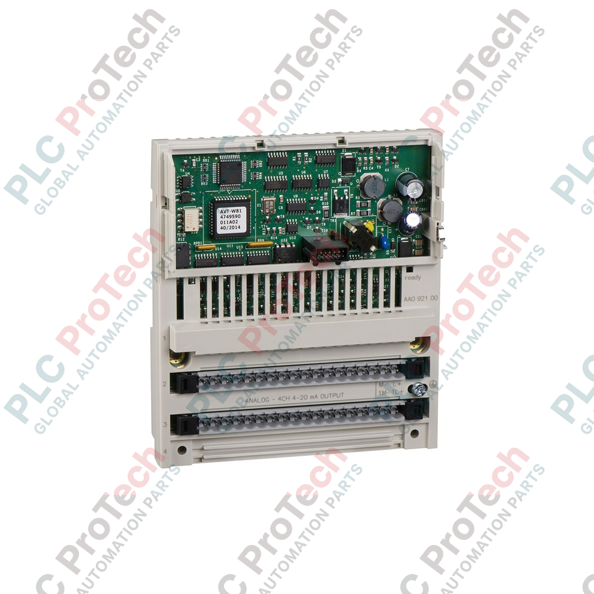
Executing precise current loop control in distributed control architectures, the Schneider Electric 170AAO92100 serves as a high-reliability 4-channel analog output module within the Modicon Momentum series. This hardware component converts digital control signals from the processor or network adapter into 4-20 mA analog outputs, allowing seamless interface connection to control valves, variable speed drives, actuators, and analog indicators. Engineered for modular flexibility, this unit clips directly onto a Momentum communication adapter or processor base, reducing field wiring complexity and optimizing cabinet panel footprint.
Features
-
Four Independent Channels: Multi-channel output capabilities manage up to four distinct 4-20 mA field loops simultaneously.
-
Modular Architecture: Integrates directly with Modicon Momentum network adapters (including Modbus TCP, Modbus Plus, and PROFIBUS) or local processor adapters.
-
High Resolution Conversion: Accurate 12-bit digital-to-analog converter ensures fine-grained control over external analog field devices.
-
Hot-Swapping Capability: Supports field-level servicing without interrupting system-wide communications when combined with compatible bases.
-
Integrated Status Diagnostics: Front-panel LED indication simplifies hardware status validation and channel fault isolation during active commissioning.
Applications
-
Modulating Control Valves: Precise positioning of pneumatic and electrical valves in chemical and water treatment facilities.
-
VFD Speed Referencing: Dynamic control over variable frequency drive speeds in conveyor systems and pumping stations.
-
Remote Field Distribution: Standardized analog field signaling in decentralized I/O networks spanning large factory floors.
-
SCADA Integration: Local analog signal reconstruction for instrumentation displays and environmental recording systems.
Technical Specifications
| Parameter |
Specification Value |
| Manufacturer |
Schneider Electric |
| Part Number / SKU |
170AAO92100 |
| Product Range |
Modicon Momentum |
| Module Type |
Distributed Analog Output Module |
| Number of Outputs |
4 Channels |
| Output Range |
4 to 20 mA |
| Resolution |
12-bit |
| External Power Requirement |
24 VDC (Loop Power) |
| Country of Origin |
France |
| Commodity Code |
85381000 |
| Shipping Weight (Calculated) |
0.38 kg |
| Package Dimensions (Calculated) |
26.0 x 18.0 x 5.5 cm |
Empirical Engineering Insights
Alternative Models & Compatibility
This module functions as a direct drop-in replacement across legacy Momentum field bus architectures. When migrating older systems to modern Modicon M580 controllers via Ethernet adapters, confirm that the network adapter head module firmware supports the 12-bit diagnostic registers mapped by the 170AAO92100 to prevent system configuration mismatches during hardware assembly scans.
Application Pitfalls & Engineering Notes
A common point of failure in field installations is the loss of external 24 VDC loop power. While the internal logic of the module remains powered through the network base adapter (allowing bus communication to remain active), a failure of the external loop power supply drops outputs to 0 mA. This can cause downstream devices to interpret the loss of signal as a broken wire fault (below the 4 mA limit threshold).
Commissioning & Wiring Tips
Always route the 4-20 mA field cables away from high-voltage AC motor lines to prevent electromagnetic induction from distorting output values. Ensure that cable shielding is terminated strictly at the local panel single-point ground. Shield grounding at both ends should be avoided to eliminate ground loop current interferences.
Installation Guidelines
CRITICAL WARNING: De-energize all primary, secondary, and external loop power sources connected to the Momentum base before mounting or removing the module. Failure to fully isolate field-level power can cause internal circuit damage or generate unexpected physical actuator movement in online process hardware.
1
Align the rear locating pins of the 170AAO92100 with the corresponding mounting slots on the pre-installed Momentum terminal base or communication adapter.
2
Press the module firmly down until the side locking tabs fully engage, confirming a secure structural and electrical connection to the underlying unit.
3
Terminate the external 4-20 mA signal loops and the auxiliary 24 VDC power supply to the designated terminals, adhering to the torque specifications on the connection diagram.
4
Apply external 24 VDC power followed by backplane network power, and verify the physical LED indicator sequence to ensure error-free channel initialization.