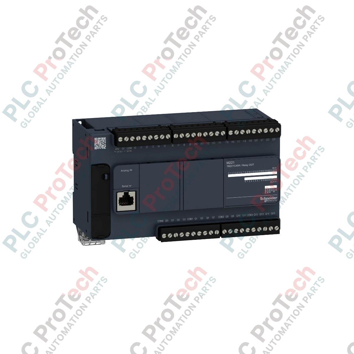
Description
Designed to handle centralized discrete automation tasks, the Schneider Electric TM221C40R serves as a high-density, AC-powered main processing unit within the Modicon M221 logic controller range. This compact base controller features 40 integrated discrete I/O channels, consisting of 24 digital inputs and 16 relay outputs, complemented by 2 high-speed analog inputs. Optimized for small-to-medium industrial architectures, it provides robust control capabilities while minimizing cabinet space usage.
Features
-
High-Density Discrete I/O: Built-in 24 discrete inputs (conforming to IEC 61131-2 Type 1) and 16 robust relay outputs.
-
Integrated Analog Inputs: Two onboard 0 to 10 V analog inputs for basic sensor integration without extra modules.
-
Flexible Communications: Features embedded RJ45 Ethernet, RJ45 serial link (RS232/RS485), and Mini-B USB programming ports.
-
Expandable Architecture: Supports Modicon TM3 expansion modules for additional I/O, safety, or communication configurations.
-
Memory Backup: Dedicated SD card slot for quick application transfer, data logging, and firmware updates.
Applications
-
Material Handling: Controls conveyor speeds, sorting systems, and small packaging machines.
-
Pumping and HVAC: Manages fluid levels, pressure loops, and fan control systems.
-
Machine Tool Automation: Integrates discrete sensor arrays and mechanical actuation switches.
-
Infrastructure Utilities: Ideal for distributed utility monitoring and auxiliary control panels.
Technical Specifications
| Parameter |
Value / Rating |
| Manufacturer |
Schneider Electric |
| Product Range |
Modicon M221 |
| Model / SKU |
TM221C40R |
| Supply Voltage Range |
100 to 240 V AC |
| Discrete Input Count |
24 (including 4 fast inputs) |
| Discrete Output Type |
Relay (Normally Open) |
| Discrete Output Count |
16 Relay Outputs |
| Analog Input Range |
2 inputs (0 to 10 V), 10-bit resolution |
| Relay Output Current |
2 A per output (maximum) |
| Programming Software |
EcoStruxure Machine Expert - Basic |
| Operating Temperature |
-10 to 55 degC (horizontal mounting) |
| Shipping Weight (Calculated) |
0.83 kg |
| Package Dimensions (Calculated) |
21.1 cm x 14.1 cm x 11.4 cm |
Connections and Interfaces
| Terminal / Port |
Assignment / Function |
| L, N |
AC Power Supply Mains Connection (100 to 240 V AC) |
| FG |
Functional Ground Connection |
| I0 to I23 |
Discrete Inputs (I0-I3 support High-Speed Counter functions) |
| Q0 to Q15 |
Relay Outputs (arranged in isolated common groups) |
| AI0, AI1, COM |
Analog Inputs (0 to 10 V) and shared Analog Common |
| Ethernet (RJ45) |
Modbus TCP client/server protocol access |
| Serial (RJ45) |
RS232/RS485 Serial Link communication configuration |
Empirical Engineering Insights
Alternative Models & Compatibility
The TM221C40R directly replaces older Twido modular or compact controller configurations during system modernization. When translating applications from TwidoSuite or TwidoSoft to EcoStruxure Machine Expert - Basic, pay careful attention to memory allocation variables (%MW) and input mapping offsets, as slight syntax translations are required to prevent data collision.
Application Pitfalls & Engineering Notes
Thermal dissipation limits require vertical spacing clearance of at least 50 mm above and below the controller housing. If the unit is installed vertically (90-degree rotation), the maximum ambient rating drops from 55 degC to 35 degC. Additionally, ensure transient voltage suppressors (snubbers) are wired across inductive AC loads connected to the relay outputs to prevent premature contact pitting.
Commissioning & Wiring Tips
The 0 to 10 V analog inputs (AI0, AI1) share a single ground (COM) that is tied to the internal logic ground. Using unshielded cable on these inputs in high-EMI environments can lead to control signal jitter. Always run analog signals in shielded twisted-pair (STP) cabling, grounding the shield only at the controller end.
Installation Guidelines
CRITICAL WARNING
De-energize all primary and field sensor power distribution circuits before installing or removing terminals. Verify that all residual charge has fully bled down. Failure to isolate input power paths may result in severe electrical shock, system bus errors, or permanent circuit board damage.
1
Mount the controller onto a standard 35 mm DIN rail inside a protective NEMA or IP-rated electrical enclosure. Secure the top and bottom locking clips.
2
Wire the L and N terminal connections to an isolated 100-240 V AC supply line. Connect the FG terminal directly to the enclosure ground bus.
3
Connect your field discrete inputs and outputs to their corresponding terminal blocks, verifying that the output load currents do not exceed the 2 A limit per channel.
4
Insert the programmed SD card or connect the Mini-B USB cable to download the application parameters via EcoStruxure Machine Expert - Basic.