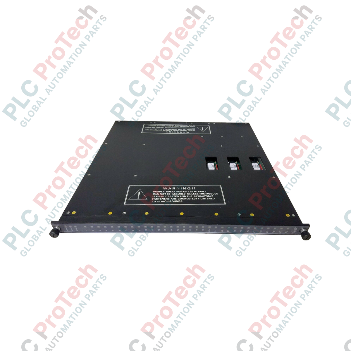
Description
For auxiliary signaling and non-triplicated isolation requirements within Tricon Safety Instrumented Systems (SIS), the Triconex 3636R provides 32 independent, non-commoned relay outputs. This simplex (non-triplicated) relay output module is designed to interface the Tricon controller with external annunciators, interposing relay panels, and auxiliary systems. By offering high-integrity galvanic isolation up to 125 VAC/VDC, the module ensures robust protection for sensitive control circuitry while managing medium-power digital signals across demanding industrial automation topologies.
Features
-
32 Isolated Channels: Individually isolated, non-commoned contacts permit the integration of multiple external voltage sources on a single module.
-
Simplex Operation: Configured as a non-triplicated (RO) module, making it highly cost-effective for non-safety critical signaling, status indicators, and alarm panels.
-
Broad Voltage Range: Supports control circuit switching up to 125 VAC or 125 VDC, offering wide compatibility with standard field devices.
-
Low Signal Compatibility: Designed with a minimum permissible load of 10 mA at 5 VDC to ensure reliable execution in low-current dry contact loops.
Applications
- Emergency Shutdown (ESD) status and alarm annunciation panels.
- Interposing relay cabinet interfacing for high-current MCC contactors.
- Distributed Control System (DCS) digital input signal isolation.
- Utility and auxiliary subsystem interlocking in petrochemical and power plants.
Technical Specifications
| Parameter |
Specification Value |
| Manufacturer |
Triconex (Schneider Electric) |
| Model Number |
3636R |
| Module Type |
Relay Output (RO) Module, Non-Triplicated |
| Number of Channels |
32, fully isolated (non-commoned) |
| Maximum Voltage |
|
Maximum Current Load |
2 A resistive, maximum per channel |
| Minimum Permissible Load |
10 mA, 5 VDC |
| Contact Type |
Normally Open (NO) / Form A |
| System Compatibility |
Tricon v9, v10, and v11 Main Chassis |
| Country of Origin |
United States |
| Shipping Weight (Calculated) |
4.0 kg (8.8 lbs) |
Connections and Interfaces
| Interface Type |
Functional Assignment / Description |
| Backplane Connector |
Dual-redundant high-density ribbon connectors interfacing with the Tricon backplane. |
| External Termination Panel (ETP) |
Field wiring connects via dedicated Triconex ETP interface cable (typically 56-pin / 96-pin connector block). |
| Channel Configuration |
32 pairs of terminal points (Output + / Output -) providing complete galvanic separation between circuits. |
Empirical Engineering Insights
Alternative Models & Compatibility
The 3636R is a simplex, non-triplicated module. Note that it cannot directly replace triplicated relay output modules like the 3625 or 3623 inside high-availability safety loops where SIL3 voting logic is mandatory. It is fully cross-compatible with standard Tricon v9 and v10 backplane chassis slots allocated for non-triplicated modules.
Application Pitfalls & Engineering Notes
When switching inductive loads such as heavy-duty solenoids or contactor coils, external arc suppression (flyback diodes for DC loads or RC snubbers for AC loads) must be installed at the load. Without adequate suppression, excessive inductive kickback can weld the non-replaceable internal mechanical relay contacts, causing the output channel to fail in a permanently energized state.
Commissioning & Wiring Tips
To prevent contact oxidation (often referred to as 'dry contact' issues), ensure that loop currents do not fall below the module's absolute minimum load parameter of 10 mA at 5 VDC. If a high-impedance digital input on a third-party PLC is being driven, consider installing an external pull-down resistor to guarantee sufficient loop current.
Installation Guidelines
CRITICAL WARNING: Prior to extracting or inserting any module, ensure the system backplane power is either isolated or verify that the chassis configuration explicitly supports hot-swapping for this non-triplicated slot. De-energize all connected external field circuits to prevent arcing across the chassis connectors during insertion. Handlers must wear a grounded ESD wrist strap at all times.
1
Inspect the module for physical damage, ensuring no debris or bent pins are present on the rear backplane connectors.
2
Align the module with the guide rails in the designated simplex slot on the Tricon main or expansion chassis.
3
Slide the module firmly into the chassis slot until the faceplate levers engage, then lock the top and bottom ejector/retractor clips to complete seating.
4
Perform a loop-back and continuity test on the external termination panel to verify circuit integrity before re-energizing field power loops.