Rendszerszintű áttekintés és működési előnyök
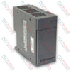
A IC695PSA040 (IC695PSA040) nagy hatásfokú, 40 wattos tápegységmodul, amelyet a GE PACSystems RX3i platformhoz terveztek. A 85–264 VAC vagy 100–300 VDC univerzális bemeneti feszültségtartományból működő modul közvetlenül az alaplapon keresztül biztosít stabil energiaelosztást a helyi feldolgozó- és I/O-egységek számára. Az automatizált vízkezelő üzemekben, vegyipari létesítményekben és gyártósori összeszerelő üzemekben végzett ipari műveletek a IC695PSA040 (IC695PSA040) modulra támaszkodnak annak érdekében, hogy a vezérlő működése kiszámítható maradjon ingadozó hálózati tápellátás mellett is. A tápegységmodul elszigeteli a belső rackszekrény-elektronikát a terepi elektromos zajtól, hő- vagy terhelési stressz esetén közvetlenül a CPU-táblázatokba naplózza az előrejelző hibákat, és beépített áthidalási képességet biztosít. Ez az architekturális ellenálló képesség megakadályozza a PLC hirtelen leállását, védi a kritikus futásidejű paramétereket, és jelentősen csökkenti a költséges, nem tervezett üzemleállásokat.
Architekturális infrastruktúra és belső védelem
Az IC695PSA040 modul hardveres felépítésének középpontjában a lokalizált háromtápsínes kimenetkezelés és az automatikus elektronikus védelem áll.
-
Háromtápsínes feszültségkimenet: Függetlenül biztosítja a +5,1 VDC és a +3,3 VDC feszültséget az RX3i rendszermoduljainak igényeihez, valamint külön +24 VDC relékimeneti ágat biztosít a külső kimeneti relémodulok táplálására.
-
Aktív túláramvédelem: Beépített elektronikus áramkorlátozással rendelkezik, amely a 5,1 VDC-s sínt 7 amperben, a 3,3 VDC-s sínt pedig 10 amperben korlátozza. Túlterhelés vagy rövidzárlat esetén a tápegység automatikusan leáll, majd folyamatos automatikus újraindítási kísérleteket kezdeményez mindaddig, amíg a kiváltó terepi hiba meg nem szűnik.
-
Átfogó állapotdiagnosztika: Négy, élvonalbeli LED-es állapotjelzőt és belső diagnosztikai reléket tartalmaz, amelyek a túlmelegedésről, a túlterhelésről és a belső komponensek állapotáról valós idejű információkat továbbítanak közvetlenül a központi CPU hibajegyzékébe.
Teljesítményadatok és hardvermátrix
| Mérnöki index |
Műszaki specifikáció |
| Modellszám |
IC695PSA040 |
| Márkaazonosító |
GE PACSystems (General Electric) |
| Vezérlőrendszer-sorozat |
RX3i vezérlők |
| Névleges összteljesítmény |
Összesen legfeljebb 40 W |
| Névleges bemeneti érték |
120/240 VAC vagy 125 VDC |
| Váltakozó áramú bemeneti tartomány |
85–264 VAC |
| Egyenáramú bemeneti tartomány |
100–300 VDC |
| Maximális bemeneti teljesítmény |
Teljes terhelés mellett legfeljebb 70 W |
| Bekapcsolási áram küszöbértéke |
Legfeljebb 4 A 250 milliszekundumig |
| Kimeneti áram specifikációi |
5,1 VDC (0–6 A), 3,3 VDC (0–9 A), 24 VDC (0–1,6 A) |
| Feszültséghatárok |
5,1 VDC (5,0–5,2 VDC), 3,3 VDC (3,1–3,5 VDC), 24 VDC (19,2–28,8 VDC) |
| Galvanikus leválasztás |
250 VAC folyamatosan (1500 VAC 1 percig a bemenettől a hátlapig) |
| Áthidalási időtartam |
Forráskimaradás esetén legalább 20 ms |
| Helyszíni vezetékezési tartomány |
Terminálonként 14–22 AWG méretű tömör vezeték |
| Láncba kapcsolható egységek száma |
Legfeljebb 4 PSA040 egység |
| Üzemi levegőre vonatkozó határértékek |
0–60 °C (külső környezeti hőmérséklet) |
| ATEX-védelmi kód |
II 3 G Ex nA IIC T3C |
| Származási ország |
Egyesült Államok |
Gyakran ismételt kérdések a műszaki diagnosztikáról
Konfigurálható-e az IC695PSA040 tápegység párhuzamos elrendezésben N+1 redundancia eléréséhez?
Nem. Ezt a konkrét tápegységet kizárólag önálló működésre tervezték RX3i Universal Backplane (IC695 terméksorozat) használata esetén. A rendszer kapacitásának növelése vagy hardveres redundancia biztosítása érdekében nem párosítható más tápegységekkel. A régebbi változatok (IC695PSA040C és korábbi) másik tápegységgel azonos hátlaphelyen történő együttes üzemeltetése súlyos berendezéskárosodást okozhat.
Mi okozza, hogy a fő tápellátásjelző LED folyamatos zöldről borostyánsárgára vált?
A zöld fény jelzi, hogy a modul feszültség alatt van, és stabil egyenáramú tápfeszültséget biztosít a hátlap számára. A borostyánsárga fény azt jelzi, hogy a bemeneti tápellátás megfelelően csatlakozik a modul bemeneti sorkapcsaihoz, de az előlapi kapcsoló KI állásban van, ezért a rack nem kap tápellátást.
Milyen mögöttes rendszerszintű meghibásodások okozhatnak teljes leállást anélkül, hogy külső LED-hibajelzés jelenne meg?
A bemeneti vezetékben egy nem javítható belső olvadóbiztosító-összekötő található végső hardveres tartalék védelemként. Bár a modul általában elektronikus lekapcsolást hajt végre, mielőtt ez a biztosító meghibásodna, egy szélsőséges belső alkatrész-rövidzárlat vagy túlzott bemeneti túlfeszültségi tranziens véglegesen megszakíthatja ezt az összekötőt. A biztosító kiolvadásakor minden működési jelzés megszűnik, és a modult fizikailag ki kell cserélni.
Helyszíni mérnöki és karbantartási protokoll
-
Áramütés veszélyének csökkentése és a be-/kikapcsolás biztonsága:
AC-tápforrással történő aktív működés közben veszélyes feszültségek (120 VAC vagy 240 VAC) vannak jelen a modul belső áramköri részein. A frontoldali sorkapocs-hozzáférési ajtónak normál működés közben zárva kell maradnia a halálos áramütés veszélyének megelőzése érdekében. Ne feledje, hogy az ajtó mögött található elülső BE/KI billenőkapcsoló csak a másodlagos egyenáramú kimeneti fokozatokat vezérli; NEM választja le a feszültség alatt álló bejövő hálózati tápellátást a sorkapcsokról.
-
Vezetékek behelyezése és meghúzási nyomatékhatárok:
Minden vezeték csupaszított szakaszának hossza legalább 9–11 mm legyen. Győződjön meg arról, hogy a vezeték teljesen be van illesztve a sorkapocs házába, amíg a vezeték szigetelése egy szintbe nem kerül a belső szigetelési ütközővel. Óvatosan húzza meg a csavaros szorítókat, ügyelve arra, hogy ne lépje túl a legnagyobb megengedett 0,5 N-m (4,4 hüvelyk-font) meghúzási nyomatékot. A nem megfelelő behelyezés miatt a csavaros szorító a vezeték szigetelésére szorulhat, ami szakadt áramkörökhöz vagy túlmelegedő csatlakozási pontokhoz vezethet.
-
Túlfeszültség-védelmi átkötés és a Hi-pot vizsgálat menete:
Az alsó sorkapcsok Metal Oxide Varistor (MOV) túlfeszültség-védelmi áramkört tartalmaznak, amelyet a felhasználó által beszerelt átkötéssel a készülékváz földelésére kell csatlakoztatni az alapvető bemeneti túlfeszültség-védelemhez. A tápegységen végzett nagyfeszültségű (Hi-pot) szigetelési vizsgálathoz ezt a túlfeszültség-védelmi áramkört az átkötés eltávolításával ki kell kapcsolni. A tranziens védelem helyreállításához a vizsgálat befejezése után azonnal szerelje vissza a földelő átkötést.