ABB

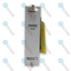
ABB SDCS-POW-4 64162993 Power Supply Board

SKU SDCS-POW-4

Disponibile
  • 12-month warranty
  • Free returns within 30 days
  • Manufacturer: ABB
  • Product No.: SDCS-POW-4
  • Origin China
  • Product Type: Power Supply
  • Barcode: 8537101190
  • Payment: T/T, Western Union
  • Weight: 0.386 kg
  • Dimensions: 23 cm x 11 cm x 3.4 cm
  • Shipping port: Xiamen
  • Warranty: 12 months

Tags

Product Documentation

Technical Datasheet (PDF) Complete specifications and technical drawings.

Technical Datasheet

ABB SDCS-POW-4 64162993 Power Supply Board

Quantità

Product Description

Description

The SDCS-POW-4 functions as a dedicated internal auxiliary power supply module engineered for large-scale industrial industrial DC drives. Mounted within the electronics tray assembly, this power supply board converts incoming line potentials to distribute all necessary isolated auxiliary operating voltages across the main controller framework and connected peripheral option modules.

The module incorporates an advanced multi-channel design to isolate high-power switching disturbances from delicate logic circuits, preventing harmonic interference from degrading drive feedback processing loops. It features dedicated power distribution pathways for fan execution infrastructure, alongside hardwired interface layers like integrated digital relay outputs and motor thermal protection (PTC) sensor loops to guarantee stable hardware diagnostics under highly volatile industrial torque loads.

For more detailed technical specifications, wiring information, and performance data, please refer to the official datasheet below:
https://cdn.shopify.com/s/files/1/0953/3227/0443/files/SDCS-POW-4.pdf?v=1781437276

Features

  • Comprehensive Voltage Generation: Natively handles conversion matrices to feed centralized logic boards and drive option modules simultaneously.
  • Hardware Thermistor Integration: Embeds direct PTC sensor interface terminals to continuously monitor motor thermal status.
  • Onboard Diagnostic Relay: Equipped with a hardware-mapped DO8 digital relay output terminal block for instantaneous safety state tracking.

Applications

  • Auxiliary sub-system voltage regulation inside DCS800 industrial DC drive platforms.
  • Power management across heavy-duty frame architectures encompassing module sizes D5, D6, and D7.
  • Integrated thermal protection interfacing for high-power DC motor applications.

Technical Specifications

Parameter Specification
Manufacturer ABB
Model Designation SDCS-POW-4
Device Classification Power Supply Board
Compatible Drive Series DCS800
Compatible Frame Sizes D5, D6, D7
Mounting Location Electronic Tray Assembly
Integrated I/O Channels 1x Relay Output (DO8), 1x PTC Input Loop
Part Type Status New

Connections and Interfaces

Connector / Interface Code Function Description
X137 Incoming Auxiliary Supply Voltage Input Terminal
X37 Main Line Voltage Potential Sensing and Reference Link
X14 Integrated Digital Relay Output Terminal Block (DO8 Contact)
PTC Terminals Motor Thermal Protection Sensor Input Interface Loop
Jumper X3 / X4 / X5 Hardware Configuration Jumpers for Internal Parameter Scaling

Installation Guidelines

  • Hazardous Voltage Discharge: Disconnect all major three-phase input feeds and any external auxiliary supply lines leading to the X137 terminal block. Note that the X37 sensing block links directly to active line potential. Wait a minimum of 15 minutes for internal bus capacitors to discharge completely, and verify zero voltage before servicing the electronic tray.
  • Electrostatic Discharge Safeguards: This board contains highly sensitive integrated circuitry susceptible to static damage. Maintenance technicians must wear a properly grounded ESD wrist strap and avoid direct physical contact with conductive traces or connector pins during substitution routines.
  • Mechanical Seating: Securely position the card onto its native slots within the drive electronics tray. Ensure all fixing screws are engaged and uniformly torqued to guarantee complete systemic grounding connection via the chassis frame.
  • Jumper Alignment Verification: Prior to re-energizing the auxiliary line, check that the hardware configuration jumpers (X3, X4, X5) are correctly positioned to match the specific voltage specifications of the host drive model.
Shipping & Returns

Global Express Shipping

  • Standard Delivery: 4–6 business days via DHL, FedEx, and UPS.
  • Express Dispatch: Same-day dispatch for in-stock orders placed before 2:00 PM (GMT+8).
  • Worldwide Coverage: Serving over 150 countries.

Returns & Warranty

  • 30-Day Guarantee: Returns accepted for in-stock products in original, factory-sealed packaging.
  • 12-Month Warranty: Every industrial component is backed by our technical warranty.
FAQ
What is the primary technical function of the SDCS-POW-4 board?
The board operates as the central auxiliary power supply unit for the drive assembly, generating and distributing all necessary internal voltage levels required by the main processor card and connected options.
Which specific drive series and frame sizes are compatible with this power board?
This module is explicitly designed for the ABB DCS800 DC drive series, specifically supporting high-power converter frame designations D5, D6, and D7.
Where is this module physically located within the converter assembly?
The board is engineered for direct mechanical mounting within the dedicated electronics tray layout of the drive chassis.
Which terminal block handles the incoming auxiliary supply power connection?
The incoming auxiliary operating power lines interface directly via the onboard terminal plug designated as X13.
What is the technical purpose of the X37 connector on this assembly?
The X37 connector links directly to active line potential tracks to provide accurate internal phase voltage sensing and synchronization reference data for the drive control loops.
What integrated motor protection capability does this board offer?
The card includes a specialized, hardwired PTC thermistor terminal loop designed to accept direct temperature feedback from the connected DC motor windings.
Does this power supply board contain an integrated digital output contact?
Yes, the module features a dedicated onboard relay output contact labeled as DO8, accessible via terminal interface block X14.
What specific hardware items should be checked before running power through a replacement board?
Technicians must verify that configuration jumpers X3, X4, and X5 are properly aligned to match the host drive frame specifications to ensure correct voltage scaling.
What safety precaution must be observed regarding the X37 interface during maintenance?
The X37 connector is tied to high line potential; therefore, absolute input isolation and full capacitor discharge verification are mandatory before touching the board.
How is structural grounding established for this specific power card?
Grounding is accomplished mechanically through the chassis support standoffs, requiring all retention screws to be firmly torqued to the electronics tray frame.
Reviews

SDCS-POW-4

Stock & lead time on request

Call
1 su 3

ABB SDCS-POW-4 64162993 Power Supply Board

Only 4 item(s) left in stock
  • Manufacturer: ABB

  • Product No.: SDCS-POW-4

  • Country of origin:China

  • Product Type: Power Supply

  • Barcode: 8537101190

  • Payment: T/T, Western Union

  • Weight: 386g

  • Dimensions: 23 cm x 11 cm x 3.4 cm

  • Shipping port: Xiamen

  • Warranty: 12 months

Quantità
Visualizza dettagli completi

Product Description

Description

The SDCS-POW-4 functions as a dedicated internal auxiliary power supply module engineered for large-scale industrial industrial DC drives. Mounted within the electronics tray assembly, this power supply board converts incoming line potentials to distribute all necessary isolated auxiliary operating voltages across the main controller framework and connected peripheral option modules.

The module incorporates an advanced multi-channel design to isolate high-power switching disturbances from delicate logic circuits, preventing harmonic interference from degrading drive feedback processing loops. It features dedicated power distribution pathways for fan execution infrastructure, alongside hardwired interface layers like integrated digital relay outputs and motor thermal protection (PTC) sensor loops to guarantee stable hardware diagnostics under highly volatile industrial torque loads.

For more detailed technical specifications, wiring information, and performance data, please refer to the official datasheet below:
https://cdn.shopify.com/s/files/1/0953/3227/0443/files/SDCS-POW-4.pdf?v=1781437276

Features

  • Comprehensive Voltage Generation: Natively handles conversion matrices to feed centralized logic boards and drive option modules simultaneously.
  • Hardware Thermistor Integration: Embeds direct PTC sensor interface terminals to continuously monitor motor thermal status.
  • Onboard Diagnostic Relay: Equipped with a hardware-mapped DO8 digital relay output terminal block for instantaneous safety state tracking.

Applications

  • Auxiliary sub-system voltage regulation inside DCS800 industrial DC drive platforms.
  • Power management across heavy-duty frame architectures encompassing module sizes D5, D6, and D7.
  • Integrated thermal protection interfacing for high-power DC motor applications.

Technical Specifications

Parameter Specification
Manufacturer ABB
Model Designation SDCS-POW-4
Device Classification Power Supply Board
Compatible Drive Series DCS800
Compatible Frame Sizes D5, D6, D7
Mounting Location Electronic Tray Assembly
Integrated I/O Channels 1x Relay Output (DO8), 1x PTC Input Loop
Part Type Status New

Connections and Interfaces

Connector / Interface Code Function Description
X137 Incoming Auxiliary Supply Voltage Input Terminal
X37 Main Line Voltage Potential Sensing and Reference Link
X14 Integrated Digital Relay Output Terminal Block (DO8 Contact)
PTC Terminals Motor Thermal Protection Sensor Input Interface Loop
Jumper X3 / X4 / X5 Hardware Configuration Jumpers for Internal Parameter Scaling

Installation Guidelines

  • Hazardous Voltage Discharge: Disconnect all major three-phase input feeds and any external auxiliary supply lines leading to the X137 terminal block. Note that the X37 sensing block links directly to active line potential. Wait a minimum of 15 minutes for internal bus capacitors to discharge completely, and verify zero voltage before servicing the electronic tray.
  • Electrostatic Discharge Safeguards: This board contains highly sensitive integrated circuitry susceptible to static damage. Maintenance technicians must wear a properly grounded ESD wrist strap and avoid direct physical contact with conductive traces or connector pins during substitution routines.
  • Mechanical Seating: Securely position the card onto its native slots within the drive electronics tray. Ensure all fixing screws are engaged and uniformly torqued to guarantee complete systemic grounding connection via the chassis frame.
  • Jumper Alignment Verification: Prior to re-energizing the auxiliary line, check that the hardware configuration jumpers (X3, X4, X5) are correctly positioned to match the specific voltage specifications of the host drive model.

Product Documentation

Technical Datasheet (PDF) Complete specifications and technical drawings.

Technical Datasheet

ABB SDCS-POW-4 64162993 Power Supply Board

What is the primary technical function of the SDCS-POW-4 board?

The board operates as the central auxiliary power supply unit for the drive assembly, generating and distributing all necessary internal voltage levels required by the main processor card and connected options.

Which specific drive series and frame sizes are compatible with this power board?

This module is explicitly designed for the ABB DCS800 DC drive series, specifically supporting high-power converter frame designations D5, D6, and D7.

Where is this module physically located within the converter assembly?

The board is engineered for direct mechanical mounting within the dedicated electronics tray layout of the drive chassis.

Which terminal block handles the incoming auxiliary supply power connection?

The incoming auxiliary operating power lines interface directly via the onboard terminal plug designated as X13.

What is the technical purpose of the X37 connector on this assembly?

The X37 connector links directly to active line potential tracks to provide accurate internal phase voltage sensing and synchronization reference data for the drive control loops.

What integrated motor protection capability does this board offer?

The card includes a specialized, hardwired PTC thermistor terminal loop designed to accept direct temperature feedback from the connected DC motor windings.

Does this power supply board contain an integrated digital output contact?

Yes, the module features a dedicated onboard relay output contact labeled as DO8, accessible via terminal interface block X14.

What specific hardware items should be checked before running power through a replacement board?

Technicians must verify that configuration jumpers X3, X4, and X5 are properly aligned to match the host drive frame specifications to ensure correct voltage scaling.

What safety precaution must be observed regarding the X37 interface during maintenance?

The X37 connector is tied to high line potential; therefore, absolute input isolation and full capacitor discharge verification are mandatory before touching the board.

How is structural grounding established for this specific power card?

Grounding is accomplished mechanically through the chassis support standoffs, requiring all retention screws to be firmly torqued to the electronics tray frame.

Global Express Shipping

  • Standard Delivery: 4-6 Business Days via DHL, FedEx, and UPS.
  • Express Dispatch: Same-day dispatch for in-stock orders placed before 2:00 PM (GMT+8).
  • Worldwide Coverage: Serving over 150 countries, including rapid delivery to Saudi Arabia and UAE.

Returns & Warranty

  • 30-Day Guarantee: Returns accepted for in-stock products in original, factory-sealed packaging.
  • 12-Month Warranty: Every industrial component is backed by our professional technical warranty.

Orders are processed and delivered Monday-Friday (excluding public holidays).


For full eligibility, restocking fees, and international return details, please view our official Refund & Return Policy .

TECHNICAL SPECIFICATIONS

Color pattern
Dots
Country of origin
China

Technical knowledge

1756-L73 Firmware Upgrade Guide: v19 vs v21/v31 Decision

Replacing a 1756-L73 does not automatically mean upgrading its firmware. This guide compares v19.013, v21.011 and v31.011, focusing on project compatibility, HMI communications, legacy networks and...

Implementing 3-Switch XOR Ladder Logic with Internal Bit

Implement a 3-SPST switch XOR light circuit in LogixPro or RSLogix 500 using an internal relay bit. Includes truth tables, boolean equations, and verified.

Building a Modbus RTU Network with CompactLogix and DeltaV

Integrate Allen-Bradley CompactLogix, Caterpillar ATS, and generators into DeltaV DCS over Modbus RTU. Covers ProSoft MVI69-MCM, Miille DIN266 gateways.

ONS Instruction Not Energizing OTE in Studio 5000 Ladder Logic

ONS instruction fires but the OTE coil never latches in Studio 5000 because the one-shot is only true for one scan. Use OTL/OTU or seal-in logic instead.

Kinetix 5500 EtherNet/IP Network Switch Requirements and Topology

Configure Allen-Bradley Kinetix 5500 servo drives on EtherNet/IP. Covers CIP Sync, IEEE 1588 V2 timing, Stratix selection, DLR topology, and HMI.

Moving Average Filtering in DCS and PLC Analog Control

A moving-average filter is the sliding-window smoother most instrument engineers drop into DCS and PLC analog paths. Here is how the window works, how N and sample time set lag, and when a...