Allen-Bradley

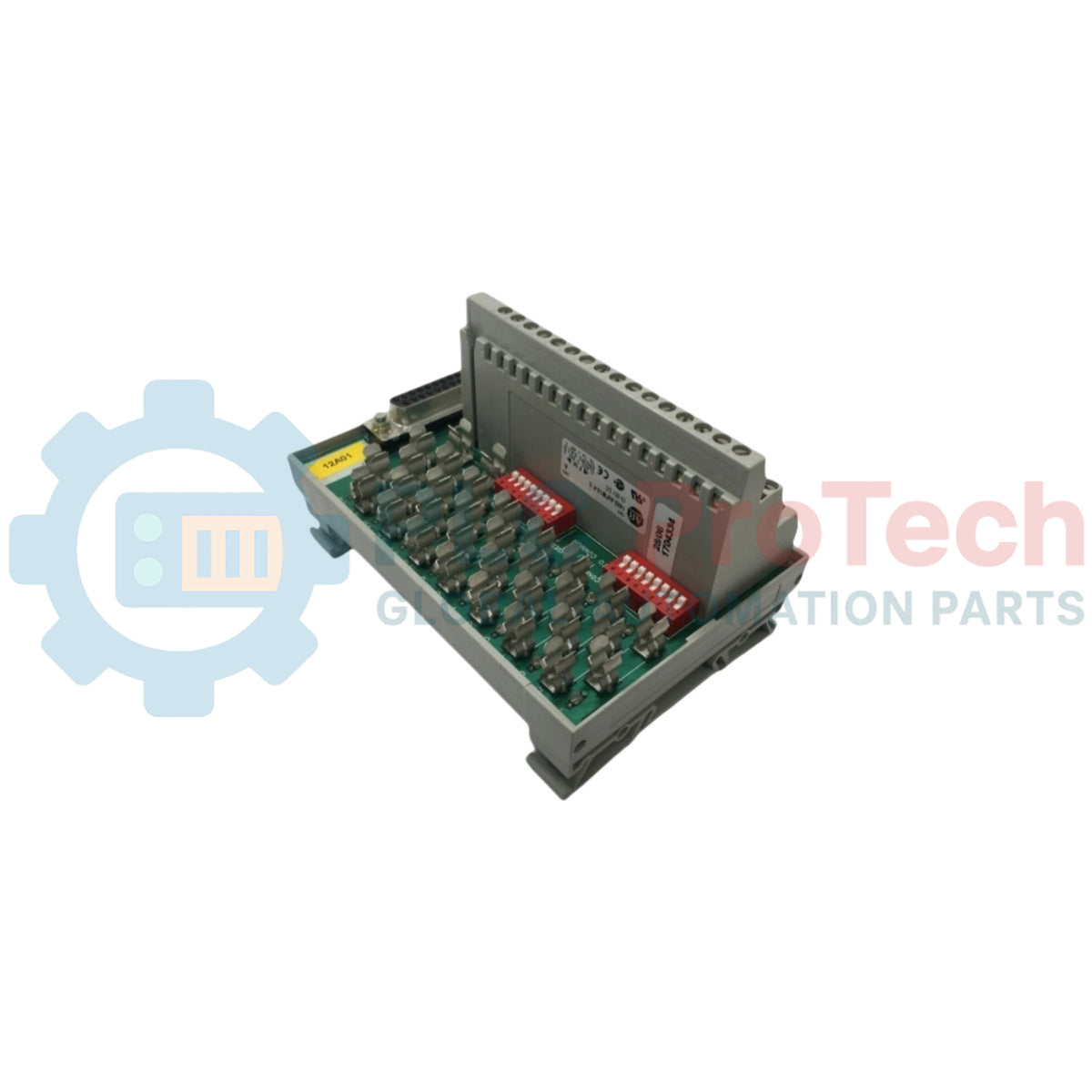
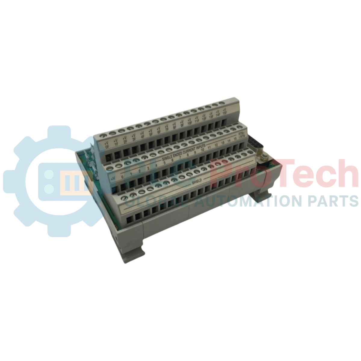
Allen-Bradley 1492-AIFM16-F-3 Analog Interface Module

SKU 1492-AIFM16-F-3

Disponibile
  • 12-month warranty
  • Free returns within 30 days
  • Manufacturer: Allen-Bradley
  • Product No.: 1492-AIFM16-F-3
  • Origin United States
  • Product Type: Analog Interface Modules
  • Barcode: 8537101190
  • Payment: T/T, Western Union
  • Weight: 0.35 kg
  • Dimensions: 83 mm x 125 mm x 71 mm (H x W x D)
  • Shipping port: Xiamen
  • Warranty: 12 months

Tags

Product Documentation

Technical Datasheet (PDF) Complete specifications and technical drawings.

Technical Datasheet

Allen-Bradley 1492-AIFM16-F-3 Analog Interface Module

Quantità

Product Description

Description

The Allen-Bradley 1492-AIFM16-F-3 is a fusible 16-channel analog input interface module designed for programmable controller wiring systems. It features integrated 24V DC blown fuse indicators and provides 3 terminals per channel for field-side signal termination. The module incorporates fuse holders for channel protection and DIP switches that allow unused inputs to be jumpered to module common on compatible analog modules.

Features

  • Fusible 16-channel input architecture with 3 terminals per channel.
  • Integrated 24V DC blown fuse indicators for rapid diagnostic field status.
  • Configurable DIP switches to jumper unused inputs to module common in the closed (ON) position.
  • Eighteen field-side shield terminals jumpered together internally and tied to the D-shell housing.
  • On-board fuse holders accommodating $5\times20\text{ mm}$ fuses.

Applications

  • Analog signal termination and channel protection for programmable controller I/O systems.
  • Field sensor wiring integration requiring individual channel fusing and blown fuse indication.

Technical Specifications

Parameter Specification
Manufacturer Allen-Bradley / Rockwell Automation
Model 1492-AIFM16-F-3
Module Type Analog Interface Module (AIFM)
Number of Inputs 16 Channels (Fusible)
Terminals per Channel 3 Terminals
Indicators 24V DC Blown Fuse Indicators
Fuse Size Capacity

5 × 20 mm

Maximum Current Rating 2 A per input, 12 A per AIFM
DIP Switch Settings Default position: OPEN/OFF/NOT jumpered together
Shield Connection 18 field-side terminals jumpered to D-shell housing

Installation Guidelines

  • Compatibility: Ensure field signal voltage and current ratings do not exceed the module specifications.
  • Fusing: Install 5 × 20 mmfuses into the integrated fuse holders before commissioning; do not exceed 2 A per input channel or 12 A total for the entire module.
  • Power Source Isolation: Note that fuse clips and blown fuse indicators connect internally to a single power source field-side terminal; all connected inputs must reference the same power source.
  • Unused Inputs Configuration: For analog modules supporting unused input jumpering, set the corresponding DIP switches to the ON position to connect unused inputs to module common.
  • Shielding: Connect cable shields to the designated field terminals to utilize the internal ground loop to the D-shell housing.
Shipping & Returns

Global Express Shipping

  • Standard Delivery: 4–6 business days via DHL, FedEx, and UPS.
  • Express Dispatch: Same-day dispatch for in-stock orders placed before 2:00 PM (GMT+8).
  • Worldwide Coverage: Serving over 150 countries.

Returns & Warranty

  • 30-Day Guarantee: Returns accepted for in-stock products in original, factory-sealed packaging.
  • 12-Month Warranty: Every industrial component is backed by our technical warranty.
FAQ
What size fuses are used with the module?
The module uses standard 5x20 mm fuses.
What are the maximum current limits for the device?
The maximum current limits are 2 A per input channel and 12 A total per AIFM module.
What function do the on-board DIP switches serve?
When closed (ON position), the DIP switches jumper unused inputs to module common for compatible analog modules.
Reviews

1492-AIFM16-F-3

Stock & lead time on request

Call
1 su 3

Allen-Bradley 1492-AIFM16-F-3 Analog Interface Module

Only 7 item(s) left in stock
  • Manufacturer: Allen-Bradley

  • Product No.: 1492-AIFM16-F-3

  • Country of origin:United States

  • Product Type: Analog Interface Modules

  • Barcode: 8537101190

  • Payment: T/T, Western Union

  • Weight: 350g

  • Dimensions: 83 mm x 125 mm x 71 mm (H x W x D)

  • Shipping port: Xiamen

  • Warranty: 12 months

Quantità
Visualizza dettagli completi

Product Description

Description

The Allen-Bradley 1492-AIFM16-F-3 is a fusible 16-channel analog input interface module designed for programmable controller wiring systems. It features integrated 24V DC blown fuse indicators and provides 3 terminals per channel for field-side signal termination. The module incorporates fuse holders for channel protection and DIP switches that allow unused inputs to be jumpered to module common on compatible analog modules.

Features

  • Fusible 16-channel input architecture with 3 terminals per channel.
  • Integrated 24V DC blown fuse indicators for rapid diagnostic field status.
  • Configurable DIP switches to jumper unused inputs to module common in the closed (ON) position.
  • Eighteen field-side shield terminals jumpered together internally and tied to the D-shell housing.
  • On-board fuse holders accommodating $5\times20\text{ mm}$ fuses.

Applications

  • Analog signal termination and channel protection for programmable controller I/O systems.
  • Field sensor wiring integration requiring individual channel fusing and blown fuse indication.

Technical Specifications

Parameter Specification
Manufacturer Allen-Bradley / Rockwell Automation
Model 1492-AIFM16-F-3
Module Type Analog Interface Module (AIFM)
Number of Inputs 16 Channels (Fusible)
Terminals per Channel 3 Terminals
Indicators 24V DC Blown Fuse Indicators
Fuse Size Capacity

5 × 20 mm

Maximum Current Rating 2 A per input, 12 A per AIFM
DIP Switch Settings Default position: OPEN/OFF/NOT jumpered together
Shield Connection 18 field-side terminals jumpered to D-shell housing

Installation Guidelines

  • Compatibility: Ensure field signal voltage and current ratings do not exceed the module specifications.
  • Fusing: Install 5 × 20 mmfuses into the integrated fuse holders before commissioning; do not exceed 2 A per input channel or 12 A total for the entire module.
  • Power Source Isolation: Note that fuse clips and blown fuse indicators connect internally to a single power source field-side terminal; all connected inputs must reference the same power source.
  • Unused Inputs Configuration: For analog modules supporting unused input jumpering, set the corresponding DIP switches to the ON position to connect unused inputs to module common.
  • Shielding: Connect cable shields to the designated field terminals to utilize the internal ground loop to the D-shell housing.

Product Documentation

Technical Datasheet (PDF) Complete specifications and technical drawings.

Technical Datasheet

Allen-Bradley 1492-AIFM16-F-3 Analog Interface Module

What size fuses are used with the module?

The module uses standard 5x20 mm fuses.

What are the maximum current limits for the device?

The maximum current limits are 2 A per input channel and 12 A total per AIFM module.

What function do the on-board DIP switches serve?

When closed (ON position), the DIP switches jumper unused inputs to module common for compatible analog modules.

Global Express Shipping

  • Standard Delivery: 4-6 Business Days via DHL, FedEx, and UPS.
  • Express Dispatch: Same-day dispatch for in-stock orders placed before 2:00 PM (GMT+8).
  • Worldwide Coverage: Serving over 150 countries, including rapid delivery to Saudi Arabia and UAE.

Returns & Warranty

  • 30-Day Guarantee: Returns accepted for in-stock products in original, factory-sealed packaging.
  • 12-Month Warranty: Every industrial component is backed by our professional technical warranty.

Orders are processed and delivered Monday-Friday (excluding public holidays).


For full eligibility, restocking fees, and international return details, please view our official Refund & Return Policy .

TECHNICAL SPECIFICATIONS

Color pattern
Greyish White
Country of origin
United States
Power source
DC Power

Technical knowledge

1756-L73 Firmware Upgrade Guide: v19 vs v21/v31 Decision

Replacing a 1756-L73 does not automatically mean upgrading its firmware. This guide compares v19.013, v21.011 and v31.011, focusing on project compatibility, HMI communications, legacy networks and...

Implementing 3-Switch XOR Ladder Logic with Internal Bit

Implement a 3-SPST switch XOR light circuit in LogixPro or RSLogix 500 using an internal relay bit. Includes truth tables, boolean equations, and verified.

Building a Modbus RTU Network with CompactLogix and DeltaV

Integrate Allen-Bradley CompactLogix, Caterpillar ATS, and generators into DeltaV DCS over Modbus RTU. Covers ProSoft MVI69-MCM, Miille DIN266 gateways.

ONS Instruction Not Energizing OTE in Studio 5000 Ladder Logic

ONS instruction fires but the OTE coil never latches in Studio 5000 because the one-shot is only true for one scan. Use OTL/OTU or seal-in logic instead.

Kinetix 5500 EtherNet/IP Network Switch Requirements and Topology

Configure Allen-Bradley Kinetix 5500 servo drives on EtherNet/IP. Covers CIP Sync, IEEE 1588 V2 timing, Stratix selection, DLR topology, and HMI.

Moving Average Filtering in DCS and PLC Analog Control

A moving-average filter is the sliding-window smoother most instrument engineers drop into DCS and PLC analog paths. Here is how the window works, how N and sample time set lag, and when a...