Allen-Bradley

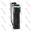
Allen-Bradley 1771-OB PLC-5 Digital DC Output Module

SKU 1771-OB

Disponibile
  • 12-month warranty
  • Free returns within 30 days
  • Manufacturer: Allen-Bradley
  • Product No.: 1771-OB
  • Origin United States
  • Product Type: Digital Output Module
  • Barcode: 8537101190
  • Payment: T/T, Western Union
  • Weight: 0.9 kg
  • Dimensions: 3.5cm x 13cm x 14.5cm
  • Shipping port: Xiamen
  • Warranty: 12 months

Tags

Quantità

Product Description

The 1771-OB is an 8-channel digital solid-state electronic device engineered for the PLC-5 / 1771 I/O Platform to drive low-voltage direct current industrial control hardware. It provides electrical switching paths for various field components, including DC motor drivers, status indicators, and industrial solenoid valves. The internal control micro-logic is energized via the local I/O chassis backplane rail, drawing a maximum current of 165 mA to maintain structural optoelectronic isolation between high-level plant field elements and core processor busses. System integration is established through the standard 1771-WA wiring arm connector assembly, permitting physical hot-swapping or card replacement sequences without disturbing landed field terminal connections.

Features

  • High-Density Output Distribution: Integrates eight independent solid-state DC switching circuits within a single-slot chassis package.
  • Dedicated Short-Circuit Protection: Individual 2 A, 8AG protective fuses mounted per channel safeguard the module against severe field overcurrent hazards.
  • Visual Status Array: Equipped with nine front-panel diagnostic LEDs providing localized visualization of blown-fuse status and specific channel conduction states.
  • Direct Input Interlocking: Supports zero-potential ground reference looping to directly drive discrete DC input modules, such as the 1771-IB receiver block.
  • Optoelectronic Backplane Protection: Incorporates continuous 1500 Vca (rms) galvanic isolation to prevent destructive external voltage transients from damaging backplane control logic.
  • Mechanical Slot Keying: Backplane socket keying fields restrict module slot alignment, ensuring only matched electrical module types sit within defined wiring nests.

Applications

  • Distributed control of factory floor solenoid-actuated pneumatic manifolds.
  • Direct activation of low-current DC motor speed control enable drives.
  • Remote instrumentation control panels and pilot lamp illumination matrix lines.
  • Inter-rack logic interlocking with low-voltage input hardware sub-assemblies.

Hardware Specifications

Parameter Specification
Manufacturer Allen-Bradley / Rockwell Automation
Model 1771-OB
Product Series PLC-5 / 1771 I/O
Module Type Digital DC Output Driver Module
Outputs Per Module 8
Chassis Compatibility 1771 I/O Chassis
Input Operational Voltage Range 10 Vdc to 27 Vdc
Output Current Capacity 1.5 A per individual output (not to exceed 8 A total per module)
Maximum Current Surge 4 A for 1 ms, repeatable at 1 s intervals
Off-State Leakage Current 1 mA maximum per output
On-State Voltage Drop 2 Vdc maximum
Signal Transmission Delay 10 ms (On to Off and Off to On states)
Power Dissipation 0.9 Watts minimum, 16.9 Watts maximum
Thermal Dissipation 3.0 BTU/h minimum, 57.6 BTU/h maximum
Backplane Logic Current Demand 165 mA @ 5 Vdc plus/minus 5%
Optoelectric Isolation 1500 Vca (rms)
Operating Temperature Range 0 degC to 60 degC
Storage Temperature Range -40 degC to 85 degC
Relative Ambient Humidity 5% to 95% (non-condensing)
Field Wiring Specifications Flexible cable with 1.5 mm2 nominal cross-section
Backplane Plastic Keying Slots Between positions 4 and 6, and between positions 18 and 20
Internal Fusing 2 A, 8AG rating (one individual fuse per output path)
Terminal Connection Block 1771-WA Wiring Arm

Connections/Interfaces

Connector Terminal Pin Function
Terminal A +DC Voltage Supply Input Reference
Terminal 0 Digital Output Channel 0 Signal Line
Terminal 1 Digital Output Channel 1 Signal Line
Terminal 2 Digital Output Channel 2 Signal Line
Terminal 3 Digital Output Channel 3 Signal Line
Terminal 4 Digital Output Channel 4 Signal Line
Terminal 5 Digital Output Channel 5 Signal Line
Terminal 6 Digital Output Channel 6 Signal Line
Terminal 7 Digital Output Channel 7 Signal Line
Terminal B DC Common Ground Return Reference

Engineering Notes

  • Terminal to Bit Discrepancy: The terminal channel designations etched on the physical 1771-WA wiring arm hardware do not directly map to software internal image register data bits. Refer strictly to the system allocation table when building control code.
  • Potential Equalization: When cross-linking an output channel directly into an input processing unit (such as a 1771-IB), a common power supply loop must feed both blocks to tie all reference grounds to an identical voltage potential.
  • Polarity Critical Warning: Correct structural polarity must be maintained on all direct current power terminals. Applying alternating current (AC) power configurations or cross-wiring polarity rails will result in critical module hardware destruction.
  • Backplane Power Balancing: The 165 mA backplane current consumption must be calculated into the aggregate power supply capacity budget of the specific 1771 chassis rack to avoid thermal overloading or backplane dip errors.

Field Guidelines

  • Electrostatic Grounding Procedures: Operators must latch an approved ESD wrist grounding strap to a structural physical ground point or discharge local potentials by touching an earth-grounded steel frame before touching card edges.
  • Plastic Keying Installation: Ensure the chassis backplane keying pegs are properly seated at the factory positions (between pins 4/6 and pins 18/20) to prevent the accidental insertion of mismatched voltage cards.
  • Chassis De-energization: Complete chassis rack power downcycles are required prior to sliding the driver module out of its physical slot to protect operators and prevent inductive backplane transients.
  • Fuse Extraction Protocol: To safely swap a compromised fuse assembly, release the front mechanical swing arm latch, withdraw the board housing, undo the two case retention screws, and replace the spent 2 A, 8AG component inside.

Technical & Procurement FAQ

Q: What specific fuse replacement specification must be used if a channel drops out? A: Each individual output switch is paired with a standard 2 A, 8AG form-factor fuse accessible underneath the card side cover.

Q: Can this DC driver module be safely slotted into the leftmost slot of a 1771 chassis? A: No, the far-left slot of the 1771 chassis configuration is structurally reserved for the master processor module or remote I/O network adapter head.

Q: Does the module display indicators on the front face for individual circuit diagnostics? A: Yes, it features one dedicated red LED for blown fuse notification alongside eight individual red status LEDs that light up when an output channel is actively energized.

Shipping & Returns

Global Express Shipping

  • Standard Delivery: 4–6 business days via DHL, FedEx, and UPS.
  • Express Dispatch: Same-day dispatch for in-stock orders placed before 2:00 PM (GMT+8).
  • Worldwide Coverage: Serving over 150 countries.

Returns & Warranty

  • 30-Day Guarantee: Returns accepted for in-stock products in original, factory-sealed packaging.
  • 12-Month Warranty: Every industrial component is backed by our technical warranty.
Reviews

1771-OB

Stock & lead time on request

Call
1 su 3

Allen-Bradley 1771-OB PLC-5 Digital DC Output Module

Only 8 item(s) left in stock
  • Manufacturer: Allen-Bradley

  • Product No.: 1771-OB

  • Country of origin:United States

  • Product Type: Digital Output Module

  • Barcode: 8537101190

  • Payment: T/T, Western Union

  • Weight: 900g

  • Dimensions: 3.5cm x 13cm x 14.5cm

  • Shipping port: Xiamen

  • Warranty: 12 months

Quantità
Visualizza dettagli completi

Product Description

The 1771-OB is an 8-channel digital solid-state electronic device engineered for the PLC-5 / 1771 I/O Platform to drive low-voltage direct current industrial control hardware. It provides electrical switching paths for various field components, including DC motor drivers, status indicators, and industrial solenoid valves. The internal control micro-logic is energized via the local I/O chassis backplane rail, drawing a maximum current of 165 mA to maintain structural optoelectronic isolation between high-level plant field elements and core processor busses. System integration is established through the standard 1771-WA wiring arm connector assembly, permitting physical hot-swapping or card replacement sequences without disturbing landed field terminal connections.

Features

  • High-Density Output Distribution: Integrates eight independent solid-state DC switching circuits within a single-slot chassis package.
  • Dedicated Short-Circuit Protection: Individual 2 A, 8AG protective fuses mounted per channel safeguard the module against severe field overcurrent hazards.
  • Visual Status Array: Equipped with nine front-panel diagnostic LEDs providing localized visualization of blown-fuse status and specific channel conduction states.
  • Direct Input Interlocking: Supports zero-potential ground reference looping to directly drive discrete DC input modules, such as the 1771-IB receiver block.
  • Optoelectronic Backplane Protection: Incorporates continuous 1500 Vca (rms) galvanic isolation to prevent destructive external voltage transients from damaging backplane control logic.
  • Mechanical Slot Keying: Backplane socket keying fields restrict module slot alignment, ensuring only matched electrical module types sit within defined wiring nests.

Applications

  • Distributed control of factory floor solenoid-actuated pneumatic manifolds.
  • Direct activation of low-current DC motor speed control enable drives.
  • Remote instrumentation control panels and pilot lamp illumination matrix lines.
  • Inter-rack logic interlocking with low-voltage input hardware sub-assemblies.

Hardware Specifications

Parameter Specification
Manufacturer Allen-Bradley / Rockwell Automation
Model 1771-OB
Product Series PLC-5 / 1771 I/O
Module Type Digital DC Output Driver Module
Outputs Per Module 8
Chassis Compatibility 1771 I/O Chassis
Input Operational Voltage Range 10 Vdc to 27 Vdc
Output Current Capacity 1.5 A per individual output (not to exceed 8 A total per module)
Maximum Current Surge 4 A for 1 ms, repeatable at 1 s intervals
Off-State Leakage Current 1 mA maximum per output
On-State Voltage Drop 2 Vdc maximum
Signal Transmission Delay 10 ms (On to Off and Off to On states)
Power Dissipation 0.9 Watts minimum, 16.9 Watts maximum
Thermal Dissipation 3.0 BTU/h minimum, 57.6 BTU/h maximum
Backplane Logic Current Demand 165 mA @ 5 Vdc plus/minus 5%
Optoelectric Isolation 1500 Vca (rms)
Operating Temperature Range 0 degC to 60 degC
Storage Temperature Range -40 degC to 85 degC
Relative Ambient Humidity 5% to 95% (non-condensing)
Field Wiring Specifications Flexible cable with 1.5 mm2 nominal cross-section
Backplane Plastic Keying Slots Between positions 4 and 6, and between positions 18 and 20
Internal Fusing 2 A, 8AG rating (one individual fuse per output path)
Terminal Connection Block 1771-WA Wiring Arm

Connections/Interfaces

Connector Terminal Pin Function
Terminal A +DC Voltage Supply Input Reference
Terminal 0 Digital Output Channel 0 Signal Line
Terminal 1 Digital Output Channel 1 Signal Line
Terminal 2 Digital Output Channel 2 Signal Line
Terminal 3 Digital Output Channel 3 Signal Line
Terminal 4 Digital Output Channel 4 Signal Line
Terminal 5 Digital Output Channel 5 Signal Line
Terminal 6 Digital Output Channel 6 Signal Line
Terminal 7 Digital Output Channel 7 Signal Line
Terminal B DC Common Ground Return Reference

Engineering Notes

  • Terminal to Bit Discrepancy: The terminal channel designations etched on the physical 1771-WA wiring arm hardware do not directly map to software internal image register data bits. Refer strictly to the system allocation table when building control code.
  • Potential Equalization: When cross-linking an output channel directly into an input processing unit (such as a 1771-IB), a common power supply loop must feed both blocks to tie all reference grounds to an identical voltage potential.
  • Polarity Critical Warning: Correct structural polarity must be maintained on all direct current power terminals. Applying alternating current (AC) power configurations or cross-wiring polarity rails will result in critical module hardware destruction.
  • Backplane Power Balancing: The 165 mA backplane current consumption must be calculated into the aggregate power supply capacity budget of the specific 1771 chassis rack to avoid thermal overloading or backplane dip errors.

Field Guidelines

  • Electrostatic Grounding Procedures: Operators must latch an approved ESD wrist grounding strap to a structural physical ground point or discharge local potentials by touching an earth-grounded steel frame before touching card edges.
  • Plastic Keying Installation: Ensure the chassis backplane keying pegs are properly seated at the factory positions (between pins 4/6 and pins 18/20) to prevent the accidental insertion of mismatched voltage cards.
  • Chassis De-energization: Complete chassis rack power downcycles are required prior to sliding the driver module out of its physical slot to protect operators and prevent inductive backplane transients.
  • Fuse Extraction Protocol: To safely swap a compromised fuse assembly, release the front mechanical swing arm latch, withdraw the board housing, undo the two case retention screws, and replace the spent 2 A, 8AG component inside.

Technical & Procurement FAQ

Q: What specific fuse replacement specification must be used if a channel drops out? A: Each individual output switch is paired with a standard 2 A, 8AG form-factor fuse accessible underneath the card side cover.

Q: Can this DC driver module be safely slotted into the leftmost slot of a 1771 chassis? A: No, the far-left slot of the 1771 chassis configuration is structurally reserved for the master processor module or remote I/O network adapter head.

Q: Does the module display indicators on the front face for individual circuit diagnostics? A: Yes, it features one dedicated red LED for blown fuse notification alongside eight individual red status LEDs that light up when an output channel is actively energized.

Global Express Shipping

  • Standard Delivery: 4-6 Business Days via DHL, FedEx, and UPS.
  • Express Dispatch: Same-day dispatch for in-stock orders placed before 2:00 PM (GMT+8).
  • Worldwide Coverage: Serving over 150 countries, including rapid delivery to Saudi Arabia and UAE.

Returns & Warranty

  • 30-Day Guarantee: Returns accepted for in-stock products in original, factory-sealed packaging.
  • 12-Month Warranty: Every industrial component is backed by our professional technical warranty.

Orders are processed and delivered Monday-Friday (excluding public holidays).


For full eligibility, restocking fees, and international return details, please view our official Refund & Return Policy .

TECHNICAL SPECIFICATIONS

Color pattern
Black
Country of origin
United States
Power source
DC Power

Technical knowledge

1756-L73 Firmware Upgrade Guide: v19 vs v21/v31 Decision

Replacing a 1756-L73 does not automatically mean upgrading its firmware. This guide compares v19.013, v21.011 and v31.011, focusing on project compatibility, HMI communications, legacy networks and...

Implementazione della logica a scala XOR con 3 interruttori e bit interno

Implementa un circuito luminoso XOR con 3 interruttori SPST in LogixPro o RSLogix 500 utilizzando un bit di relè interno. Include tabelle della verità, equazioni booleane e verifica.

Creazione di una rete Modbus RTU con CompactLogix e DeltaV

Integra Allen-Bradley CompactLogix, Caterpillar ATS e generatori nel DCS DeltaV tramite Modbus RTU. Include i gateway ProSoft MVI69-MCM e Miille DIN266.

Istruzione ONS che non attiva l’OTE nella logica ladder di Studio 5000

L’istruzione ONS si attiva, ma la bobina OTE non rimane mai eccitata in Studio 5000 perché il one-shot è vero solo per una scansione. Usa OTL/OTU oppure una logica di autoritenuta.

Requisiti e topologia dello switch di rete EtherNet/IP Kinetix 5500

Configura i servoazionamenti Allen-Bradley Kinetix 5500 su EtherNet/IP. Include CIP Sync, la temporizzazione IEEE 1588 V2, la selezione degli switch Stratix, la topologia DLR e l’HMI.

Filtraggio con media mobile nei sistemi di controllo analogico DCS e PLC

Un filtro a media mobile è lo smussatore a finestra scorrevole che la maggior parte degli ingegneri della strumentazione inserisce nei percorsi dei segnali analogici di DCS e PLC. Ecco come funziona...