


Tutto sui PLC: la CPU
A practical engineering guide to PLC CPU operation, from deterministic scan cycles and I/O image tables to memory, communications, diagnostics, redundancy, processor sizing, and reliable system...


The Allen-Bradley 80190-240-02-R functions as a high-density industrial control board micro-component deployed within medium voltage PowerFlex 7000 drive topologies to handle precise algorithmic switching and integrated long-range communications. This module processes high-speed drive commands alongside long-distance backbone optical links via a built-in 1000BaseFX Gigabit Full Duplex optical terminal network, enabling noise-immune signal transmission up to 120 kilometers. Outfitted with a 9-pin connector interface and a 10 digit dial switch utilizing strict 0/1 binary encoding, the device coordinates hardware address mapping and gating control data directly between local processors and distributed supervisor layers.
| Parameter | Specification |
|---|---|
| Manufacturer | Allen-Bradley |
| Spare Part Number | 80190-240-02-R |
| Product Category | PLC Systems |
| Power Supply Input | 12 to 48V DC |
| Communication Port Speed | 1000BaseFX Gigabit Full Duplex |
| Default Fiber Interface | SC (Optional: FC, ST) |
| Maximum Transmission Distance | Up to 120 kilometers |
| Hardware Address Interface | 10 digit dial switch (0/1 binary encoding) |
| Interface Port Count | 1 x 9-pin connector |
| Protection Level | IP30 level protection |
| Chassis Material | Metal shell |
| Installation Form Factors | Wall mounted or rail mounted installation |
| Working Temperature Range | 0 Celsius to 70 Celsius |
| Humidity Range | 10% to 95% (no condensation) |
| Country of Origin | USA |
| Tariff Code | 8537101190 |
| Weight | 0.45 kg |
| Estimated Shipping Dimensions | 30.2 x 25.3 x 3 cm |
| Connector Pin / Terminal | Function / Circuit Assignment |
|---|---|
| 9-Pin Connector | Local peripheral configuration and low-level diagnostic serial bus interface |
| Fiber Transceiver Port | 1000BaseFX Gigabit main link interface (SC connector default) |
| 10-Position Dial Matrix | Manual binary hardware node identification configuration matrix |
| Power Terminal Block | 12 to 48V DC primary operational power input pins |
Mount the IP30 metal shell housing firmly onto the designated enclosure plate via standard wall mounting screws or engage the integrated base clip straight onto standard DIN rail frameworks.
Set the 10 digit dial switch configuration positions using 0/1 binary encoding values to align with the specific station hardware node maps required by the control network.
Clean the SC fiber optic link terminals using analytical-grade fiber wipes, align the indexing keys, and insert them firmly into the transceiver till an audibly locked seating occurs.
Terminate the 12 to 48V DC power lines onto the terminal header block while preserving exact polarity settings, then secure the terminal safety set screws.
Establish a low-impedance grounding strap connection from the IP30 structural metal housing to the central earth ground matrix of the drive assembly cabinet.
Global Express Shipping
Returns & Warranty


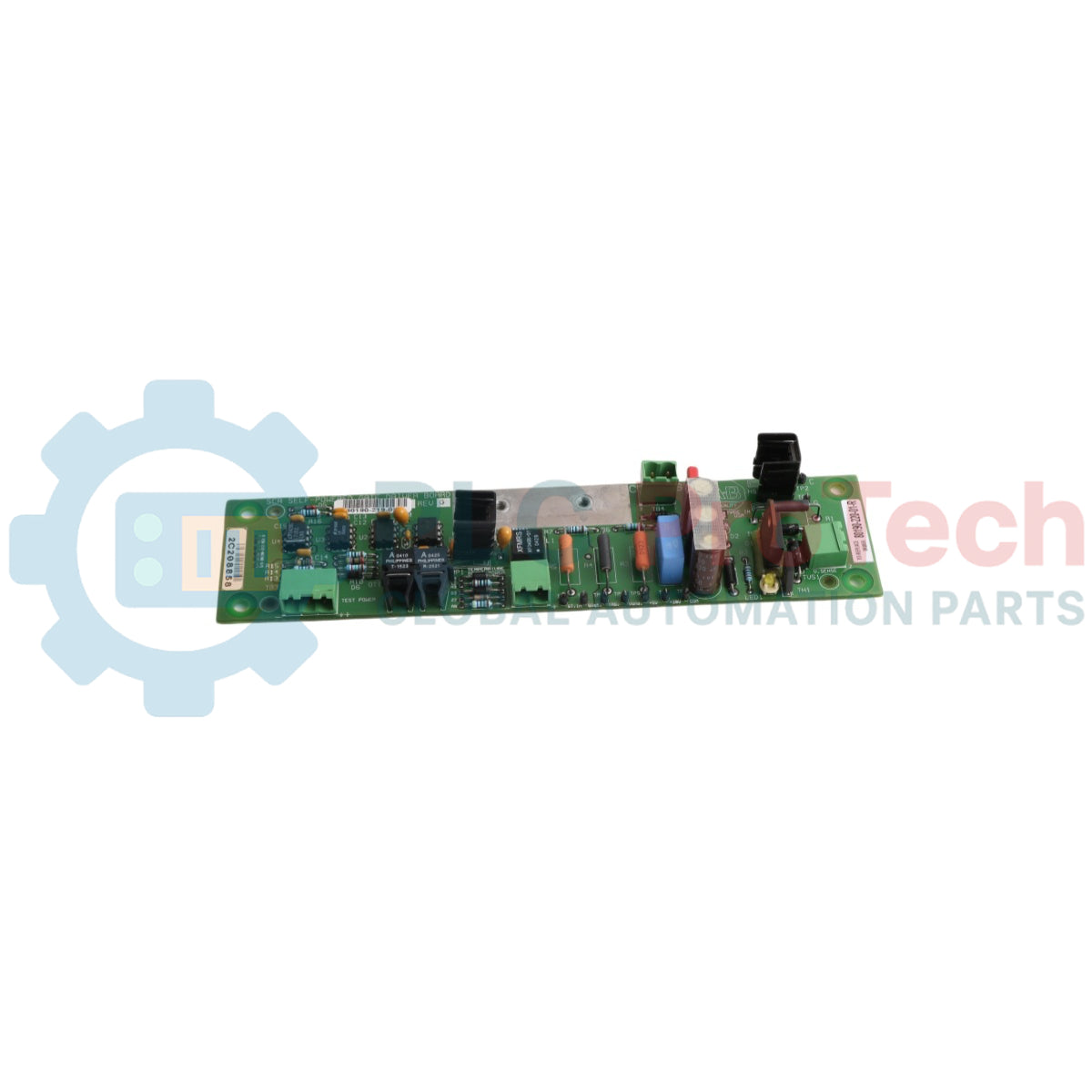


Manufacturer: Allen-Bradley
Product No.: 80190-240-02-R
Country of origin:United States
Product Type: Powerflex Control Board
Barcode: 8537101190
Payment: T/T, Western Union
Weight: 450g
Dimensions: 30.2 x 25.3 x 3 cm
Shipping port: Xiamen
Warranty: 12 months
The Allen-Bradley 80190-240-02-R functions as a high-density industrial control board micro-component deployed within medium voltage PowerFlex 7000 drive topologies to handle precise algorithmic switching and integrated long-range communications. This module processes high-speed drive commands alongside long-distance backbone optical links via a built-in 1000BaseFX Gigabit Full Duplex optical terminal network, enabling noise-immune signal transmission up to 120 kilometers. Outfitted with a 9-pin connector interface and a 10 digit dial switch utilizing strict 0/1 binary encoding, the device coordinates hardware address mapping and gating control data directly between local processors and distributed supervisor layers.
| Parameter | Specification |
|---|---|
| Manufacturer | Allen-Bradley |
| Spare Part Number | 80190-240-02-R |
| Product Category | PLC Systems |
| Power Supply Input | 12 to 48V DC |
| Communication Port Speed | 1000BaseFX Gigabit Full Duplex |
| Default Fiber Interface | SC (Optional: FC, ST) |
| Maximum Transmission Distance | Up to 120 kilometers |
| Hardware Address Interface | 10 digit dial switch (0/1 binary encoding) |
| Interface Port Count | 1 x 9-pin connector |
| Protection Level | IP30 level protection |
| Chassis Material | Metal shell |
| Installation Form Factors | Wall mounted or rail mounted installation |
| Working Temperature Range | 0 Celsius to 70 Celsius |
| Humidity Range | 10% to 95% (no condensation) |
| Country of Origin | USA |
| Tariff Code | 8537101190 |
| Weight | 0.45 kg |
| Estimated Shipping Dimensions | 30.2 x 25.3 x 3 cm |
| Connector Pin / Terminal | Function / Circuit Assignment |
|---|---|
| 9-Pin Connector | Local peripheral configuration and low-level diagnostic serial bus interface |
| Fiber Transceiver Port | 1000BaseFX Gigabit main link interface (SC connector default) |
| 10-Position Dial Matrix | Manual binary hardware node identification configuration matrix |
| Power Terminal Block | 12 to 48V DC primary operational power input pins |
Mount the IP30 metal shell housing firmly onto the designated enclosure plate via standard wall mounting screws or engage the integrated base clip straight onto standard DIN rail frameworks.
Set the 10 digit dial switch configuration positions using 0/1 binary encoding values to align with the specific station hardware node maps required by the control network.
Clean the SC fiber optic link terminals using analytical-grade fiber wipes, align the indexing keys, and insert them firmly into the transceiver till an audibly locked seating occurs.
Terminate the 12 to 48V DC power lines onto the terminal header block while preserving exact polarity settings, then secure the terminal safety set screws.
Establish a low-impedance grounding strap connection from the IP30 structural metal housing to the central earth ground matrix of the drive assembly cabinet.
Global Express Shipping
Returns & Warranty
Orders are processed and delivered Monday-Friday (excluding public holidays).
For full eligibility, restocking fees, and international return details, please view our official Refund & Return Policy .
| Country of origin |
United States
|

A practical engineering guide to PLC CPU operation, from deterministic scan cycles and I/O image tables to memory, communications, diagnostics, redundancy, processor sizing, and reliable system...

Sostituire un 1756-L73 non significa automaticamente aggiornare il firmware. Questa guida confronta le versioni 19.013, 21.011 e 31.011, concentrandosi sulla compatibilità dei progetti, sulle...

Implementa un circuito luminoso XOR con 3 interruttori SPST in LogixPro o RSLogix 500 utilizzando un bit di relè interno. Include tabelle della verità, equazioni booleane e verifica.

Integra Allen-Bradley CompactLogix, Caterpillar ATS e generatori nel DCS DeltaV tramite Modbus RTU. Include i gateway ProSoft MVI69-MCM e Miille DIN266.

L’istruzione ONS si attiva, ma la bobina OTE non rimane mai eccitata in Studio 5000 perché il one-shot è vero solo per una scansione. Usa OTL/OTU oppure una logica di autoritenuta.

Configura i servoazionamenti Allen-Bradley Kinetix 5500 su EtherNet/IP. Include CIP Sync, la temporizzazione IEEE 1588 V2, la selezione degli switch Stratix, la topologia DLR e l’HMI.