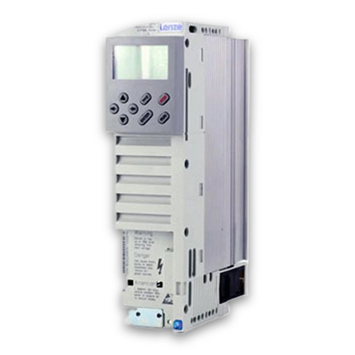
The Lenze E82EV-552K2C is a vector-controlled frequency inverter designed for variable-speed motor control in industrial machines. It belongs to the 8200 vector series and uses a built-in construction for installation within an electrical enclosure. The drive incorporates motor connections, a relay output and a motor temperature monitoring input for a PTC sensor or normally closed thermal contact.
The AIF automation interface accepts optional keypad and communication modules. The FIF function interface accepts optional Standard I/O, Application I/O or fieldbus function modules. PROFIBUS-DP and INTERBUS communication requires the corresponding optional module. Drive configuration includes motor parameter identification, adjustable acceleration and deceleration, and parameter-set management.
Features
Parameter saving, loading, copying and restoration through C0002, with drive-to-drive parameter transfer using an optional keypad.
Configurable user menu for selected operating parameters and an ALL menu for access to the complete code list.
Motor parameter identification through C0148.
Direction selection, DC injection braking and fixed setpoint selection through configured digital inputs on a suitable I/O function module.
Red and green LEDs for operating-status indication, with fault-code display available through an optional keypad.
Applications
Variable-speed motor drives installed in industrial machines and electrical systems.
Machine drives requiring adjustable acceleration, deceleration and fixed operating setpoints.
Automated installations integrating drive control through optional PROFIBUS-DP or INTERBUS communication modules.
Technical Specifications
Parameter
Specification
Manufacturer
Lenze
Product series
8200 vector
Product type
Vector-controlled frequency inverter
Construction
Built-in unit
Rated power
5.5 kW
Voltage class
230 V
Drive generation
C
Parameter sets
4
Parameter-set activation
Digital signals configured through C0410
Default control characteristic
Linear V/f
Minimum output frequency setting, C0010
Factory setting: 0.00 Hz
Maximum output frequency setting, C0011
Factory setting: 50.00 Hz
Main setpoint acceleration time, C0012
Factory setting: 5.00 s
Main setpoint deceleration time, C0013
Factory setting: 5.00 s
V/f rated frequency, C0015
Factory setting: 50.00 Hz
Connections/Interfaces
Connector Pin
Function
X1.1
Integrated terminal strip for mains connection and DC supply
X1.2
Relay-output terminal strip
X2.1
Integrated terminal strip for motor connection and optional brake resistor
X2.2
Motor PTC connection or normally closed motor thermal contact
Motor PE and shield connection at X2.1
2-pole terminal strip for motor protective earth and motor cable shield
AIF
Automation interface for optional E82ZBC keypad, EMZ9371BC keypad XT or type 21XX communication modules
AIF with optional fieldbus module
INTERBUS through module 2111 or PROFIBUS-DP through module 2133
FIF
Function interface for optional Standard I/O E82ZAFSC or Application I/O E82ZAFAC
FIF with optional fieldbus module
INTERBUS through E82ZAFIC or PROFIBUS-DP through E82ZAFPC
Installation Guidelines
Install the inverter inside an enclosure suitable for EMC-compliant installation. Maintain metallic contact between the cabinet doors and housing, and minimize unnecessary enclosure openings.
Connect protective earth and secure motor and control cable shields using the designated shield connections and clamps.
Keep cooling surfaces and ventilation openings unobstructed. Remove accumulated contamination without damaging the cooling surfaces.
Disconnect the mains and any external supplies before working on terminal blocks. Wait at least 3 minutes, then verify that power terminals, relay connections and FIF contacts are de-energized.
Connect or disconnect pluggable terminal blocks only while the inverter is isolated from its power supply.
Allow at least 3 minutes between successive mains switch-on operations.
If a residual current device is used on the supply side, use a type B device.
Configure the motor parameters and operating setpoints before enabling the drive. Perform motor parameter identification through C0148 where required by the selected operating mode.
Compliance and Certifications
Directive or Standard
Application
Low-Voltage Directive 2006/95/EC
Controller compliance
EN 61800-5-1
Applicable harmonised standard for the controller
EN 61800-3
Installation in category C2 drive systems
FAQ
Which interface accepts the keypad for parameter setting and drive diagnostics?
The AIF automation interface accepts the optional E82ZBC keypad or EMZ9371BC keypad XT. The keypad provides parameter access, operating-status indication and fault-code display.
Can the inverter communicate with a PROFIBUS-DP or INTERBUS control system?
PROFIBUS-DP and INTERBUS communication requires the corresponding optional module. Examples include PROFIBUS-DP 2133 or INTERBUS 2111 on AIF, and E82ZAFPC or E82ZAFIC on FIF.
Where should the motor temperature sensor connect on the inverter?
The motor PTC or normally closed thermal contact connects to terminal strip X2.2. This connection provides the motor temperature monitoring input.
Can the keypad select which parameter set operates the drive?
Operating parameter sets are activated by digital signals configured through C0410. The keypad can select parameter sets 1 through 4 for editing, but does not activate them for operation.
How can an existing drive configuration be copied to another inverter?
Parameter sets can be transferred between drive controllers using the optional keypad and code C0002. The same parameter-management function supports saving, loading and copying basic settings.
How long must maintenance personnel wait before checking disconnected power terminals?
Wait at least 3 minutes after disconnecting the supply, then verify that all relevant terminals are de-energized. Relay contacts may remain energized by an external supply even when the inverter mains connection is disconnected.
Una lista di controllo tecnica per sostituire un Allen-Bradley 1746-A7: verificare la serie del telaio, il carico del backplane, la disposizione degli slot, i cavi di interconnessione, il montaggio,...
Una guida alla sostituzione sul campo del GE Fanuc IC200MDL650, che tratta la logica negativa in base alla revisione, quattro gruppi comuni, le soglie a 24 VDC, il filtraggio degli ingressi, i...
Una guida alla sostituzione dell’IC697CPX935 incentrata sulle esigenze sul campo, che illustra la memoria veloce, il comportamento seriale dipendente dal firmware, l’alimentazione del rack, il...
Una guida alla sostituzione dell'IC693DSM324 sul campo, con controlli dell'unità host Series 90-30, registri della catena servo FSSB, budget di alimentazione a 5 V, limiti del firmware, controllo...
Una guida alla sostituzione di HIMA F3430, pensata per il lavoro sul campo, che tratta la portata dei contatti del relè, il declassamento per carichi CC, i fusibili, le differenze tra F3330 e F3331,...
Una guida pratica alla sostituzione dell’IC697PWR710, con calcoli del carico a 5 V, limiti dei rack doppi, cavi di estensione, controlli degli ingressi, comportamento delle protezioni e rischi legati...
Scegliendo una selezione si ottiene un aggiornamento completo della pagina.