


Replacing ABB DSQC 351: Controller and Network Checks
Checks to record before replacing ABB 3HNE 00006-1 DSQC 351: controller generation, X3/X5/X20/X21 wiring, DeviceNet settings, INTERBUS mapping, and LED states.
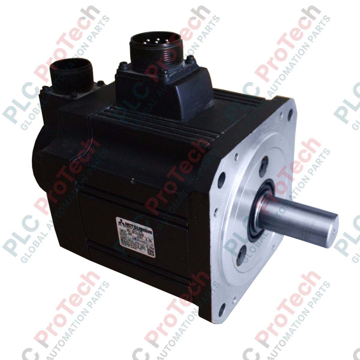
Manufacturer: Mitsubishi Electric
Product No.: HC-SFS102B
Country of origin:United States
Product Type: Motori servo AC
Payment: T/T, Western Union
Weight: 8000g
Shipping port: Xiamen
Warranty: 12 months
Progettato per il controllo del movimento industriale ad alta precisione, questo servomotore CA da 1 kW a inerzia media, il Mitsubishi Electric HC-SFS102B, offre prestazioni dinamiche affidabili nelle architetture di automazione più esigenti. Dotato di un freno elettromagnetico di mantenimento integrato, questo dispositivo è progettato per mantenere saldamente la posizione dell'albero in condizioni di assenza di alimentazione, risultando ideale per assi verticali e sistemi di posizionamento che richiedono un funzionamento a sicurezza intrinseca.
| Parametro | Valore della specifica |
|---|---|
| Produttore | Mitsubishi Electric |
| Numero di modello | HC-SFS102B |
| Serie | Serie HC-SFS (inerzia media / capacità media) |
| Potenza nominale | 1,0 kW |
| Velocità nominale | 2000 giri/min |
| Velocità massima | 3000 giri/min |
| Compatibilità della tensione di ingresso | Classe 200 V CA |
| Freno elettromagnetico | Integrato (freno di mantenimento) |
| Massa del motore | 7,0 kg (12,4 libbre) |
| Peso di spedizione (calcolato) | 8,0 kg (17,6 libbre) |
L'HC-SFS102B è progettato per essere abbinato nativamente agli amplificatori servo Mitsubishi MR-J2S-100A (analogico/a impulsi) e MR-J2S-100B (SSCNET). In caso di migrazione alle piattaforme MR-J4 o MR-J5 più recenti, si noti che la sostituzione diretta fisica ed elettrica non è supportata senza cavi di conversione specializzati e mappatura dei parametri, a causa delle differenze nei protocolli di risoluzione dell'encoder.
Il freno elettromagnetico integrato è esclusivamente un freno di mantenimento e non deve mai essere utilizzato per la decelerazione dinamica o l'arresto. Inserire il freno mentre il motore ruota ad alta velocità causerà una rapida usura per attrito, riducendo la coppia di mantenimento e provocando un guasto meccanico prematuro del gruppo freno.
Assicurarsi che il circuito di rilascio del freno sia alimentato da un alimentatore indipendente e regolato a 24 VCC, per evitare che le cadute di tensione compromettano l'inserimento del freno. Installare sempre un diodo di assorbimento dei picchi in parallelo al terminale del freno per proteggere il relè di controllo dai picchi di tensione induttiva durante i cicli di commutazione.
AVVERTENZA CRITICA:
Isolare tutte le fonti di alimentazione elettrica prima di iniziare l'installazione. Verificare che il LED di carica dell'amplificatore servo sia completamente spento. La tensione residua nei condensatori del bus CC può causare gravi scosse elettriche e danni alle apparecchiature.
Montare saldamente il motore su una base rigida della macchina, assicurando un allineamento preciso dell'albero con il giunto del carico per prevenire il sovraccarico radiale e assiale dei cuscinetti.
Collegare i cavi dell'encoder e di alimentazione utilizzando connettori originali Mitsubishi di tipo MS, di grado militare. Assicurarsi che il filo di terra sia collegato direttamente al terminale di terra di protezione dell'azionamento servo.
Verificare che il circuito di controllo del freno a 24 VCC sia cablato correttamente attraverso l'interblocco dell'uscita sequenziale dell'amplificatore servo prima di applicare l'alimentazione principale.

Global Express Shipping
Returns & Warranty


Global Express Shipping
Returns & Warranty
Orders are processed and delivered Monday-Friday (excluding public holidays).
For full eligibility, restocking fees, and international return details, please view our official Refund & Return Policy .
| Country of origin |
United States
|

Checks to record before replacing ABB 3HNE 00006-1 DSQC 351: controller generation, X3/X5/X20/X21 wiring, DeviceNet settings, INTERBUS mapping, and LED states.

Compare the IC693CPU360 and IC693CPU364 by Ethernet interface, +5 VDC load, memory, rack limits, and replacement checks.

A field-first diagnostic sequence for 1756-OF4 analog output problems: channel mode, removable terminal block, scaling, and controlled electrical checks.

A direct comparison of 1746-OA8 and 1746-OA16 output count, common grouping, backplane current and temperature-derated load limits.

A field checklist for recording the 1761-NET-DNI hardware series, firmware, EDS file, DF1 settings, DeviceNet address and messaging configuration before replacement.

The EL3062 is a 0–10 V EtherCAT terminal. The EL3062-0030 is a 0–30 V variant. This checklist covers identification, scaling and commissioning.