


Replacing ABB DSQC 351: Controller and Network Checks
Checks to record before replacing ABB 3HNE 00006-1 DSQC 351: controller generation, X3/X5/X20/X21 wiring, DeviceNet settings, INTERBUS mapping, and LED states.
Manufacturer: Mitsubishi Electric
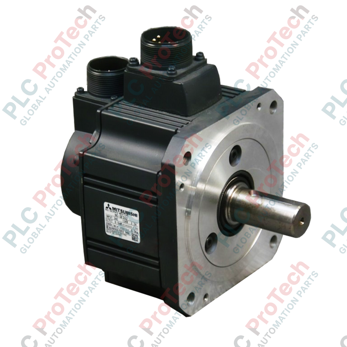
Product No.: HC-SFS352B
Country of origin:United States
Product Type: Motori servo AC
Payment: T/T, Western Union
Weight: 20000g
Dimensions: 400mm x 400mm x 20mm
Shipping port: Xiamen
Warranty: 12 months
Progettato per sistemi di posizionamento ad anello chiuso ad alta richiesta, il servomotore CA Mitsubishi Electric HC-SFS352B offre una robusta potenza di 3.5 kW combinata con caratteristiche di inerzia media. Operando nell'architettura del sistema MELSERVO-J2-Super, questo motore è ottimizzato specificamente per applicazioni che richiedono una regolazione stabile della velocità, una retroazione ad alta risoluzione e prestazioni di decelerazione precise. Il freno elettromagnetico di sicurezza integrato garantisce una forza di mantenimento strutturale durante le interruzioni di alimentazione, proteggendo gli assi meccanici critici da cadute gravitazionali impreviste o da sovracorsa causate dall'inerzia.
| Parametro | Valore |
|---|---|
| Produttore | Mitsubishi Electric |
| Identificativo del modello | HC-SFS352B |
| Serie | Serie MELSERVO HC-SFS |
| Potenza nominale | 3.5 kW |
| Velocità nominale | 2000 giri/min |
| Velocità massima | 3000 giri/min |
| Coppia nominale | 16.7 N-m |
| Freno elettromagnetico | Sì (integrato, 24 V CC, tipo di mantenimento) |
| Consumo di potenza del freno | 30 W a 20 °C |
| Classe di tensione compatibile | 200 V CA |
| Specifiche dell'encoder | 17 bit assoluto/incrementale (131.072 impulsi/giro) |
| Grado di protezione dell'involucro | IP65 (esclusa l'apertura dell'albero) |
| Peso netto | 19.0 kg |
| Peso di spedizione (calcolato) | 20.0 kg |
Questo servomotore è dotato di connettori circolari MS di tipo militare dedicati per i collegamenti di alimentazione e dell'encoder, garantendo una resistenza ai liquidi IP65 quando accoppiati correttamente.
| Tipo di connettore | Riferimento morsetti / pin | Assegnazione delle funzioni |
|---|---|---|
| Connettore di alimentazione | U | Fase motore U |
| V | Fase motore V | |
| W | Fase motore W | |
| Terra | Terra / PE Terra di protezione | |
| Connettore del freno | B1 | Morsetto del freno (non polarizzato) |
| B2 | Morsetto del freno (non polarizzato) |
L'HC-SFS352B appartiene alla linea legacy MELSERVO-J2S ed è abbinato nativamente agli amplificatori MR-J2S-350A o MR-J2S-350B. Per le migrazioni o gli aggiornamenti del sistema alle linee contemporanee, come la serie MR-J4, è necessario passare al motore HG-SR352B e agli amplificatori MR-J4-350A/B. Le sostituzioni fisiche dirette con nuovi controller richiedono cavi adattatori specifici a causa delle differenze nei protocolli di feedback dell'encoder.
Il funzionamento continuo ad alta frequenza di cicli vicino alla coppia nominale genera una quantità significativa di calore. Assicurarsi che il motore sia imbullonato direttamente a una flangia dissipatrice appropriata (l'area minima consigliata della superficie in alluminio è 400mm x 400mm x 20mm) per evitare guasti di sovraccarico termico (AL.30 o AL.46) sull'azionamento dell'amplificatore associato. Evitare di collocare il motore in involucri non ventilati senza raffreddamento esterno attivo.
Per sopprimere le interferenze elettromagnetiche (EMI) che possono attivare guasti del feedback (come AL.16 o AL.20), instradare i cavi di alimentazione del motore e i cavi dell'encoder in canaline separate in acciaio collegate a terra. Mantenere una distanza di almeno 10 cm tra queste linee. Durante la messa in servizio del freno, assicurarsi che sia alimentato tramite un alimentatore esterno isolato da 24 V CC con un diodo indipendente di soppressione dei picchi, anziché direttamente da un'uscita del PLC.
AVVERTENZA CRITICA:
Prima di iniziare l'installazione meccanica o elettrica, togliere completamente tensione all'amplificatore servo e attendere almeno 15 minuti affinché i banchi di condensatori interni si scarichino completamente. Verificare l'assenza di tensione ai morsetti del bus CC prima di intervenire su morsetti o connettori.
Fissare saldamente il motore al telaio di base della macchina, verificando l'allineamento parallelo dell'albero di uscita per prevenire l'usura prematura dei cuscinetti.
Collegare la messa a terra fisica del sistema al terminale PE dell'alloggiamento del motore, verificando che la resistenza soddisfi la norma di sicurezza industriale locale (in genere < 100 ohm).
Accoppiare i connettori circolari di tipo militare per l'alimentazione e il feedback dell'encoder, ruotando completamente l'anello di accoppiamento fino al bloccaggio per mantenere la tenuta IP65.

Global Express Shipping
Returns & Warranty


Global Express Shipping
Returns & Warranty
Orders are processed and delivered Monday-Friday (excluding public holidays).
For full eligibility, restocking fees, and international return details, please view our official Refund & Return Policy .
| Country of origin |
United States
|

Checks to record before replacing ABB 3HNE 00006-1 DSQC 351: controller generation, X3/X5/X20/X21 wiring, DeviceNet settings, INTERBUS mapping, and LED states.

Compare the IC693CPU360 and IC693CPU364 by Ethernet interface, +5 VDC load, memory, rack limits, and replacement checks.

A field-first diagnostic sequence for 1756-OF4 analog output problems: channel mode, removable terminal block, scaling, and controlled electrical checks.

A direct comparison of 1746-OA8 and 1746-OA16 output count, common grouping, backplane current and temperature-derated load limits.

A field checklist for recording the 1761-NET-DNI hardware series, firmware, EDS file, DF1 settings, DeviceNet address and messaging configuration before replacement.

The EL3062 is a 0–10 V EtherCAT terminal. The EL3062-0030 is a 0–30 V variant. This checklist covers identification, scaling and commissioning.